
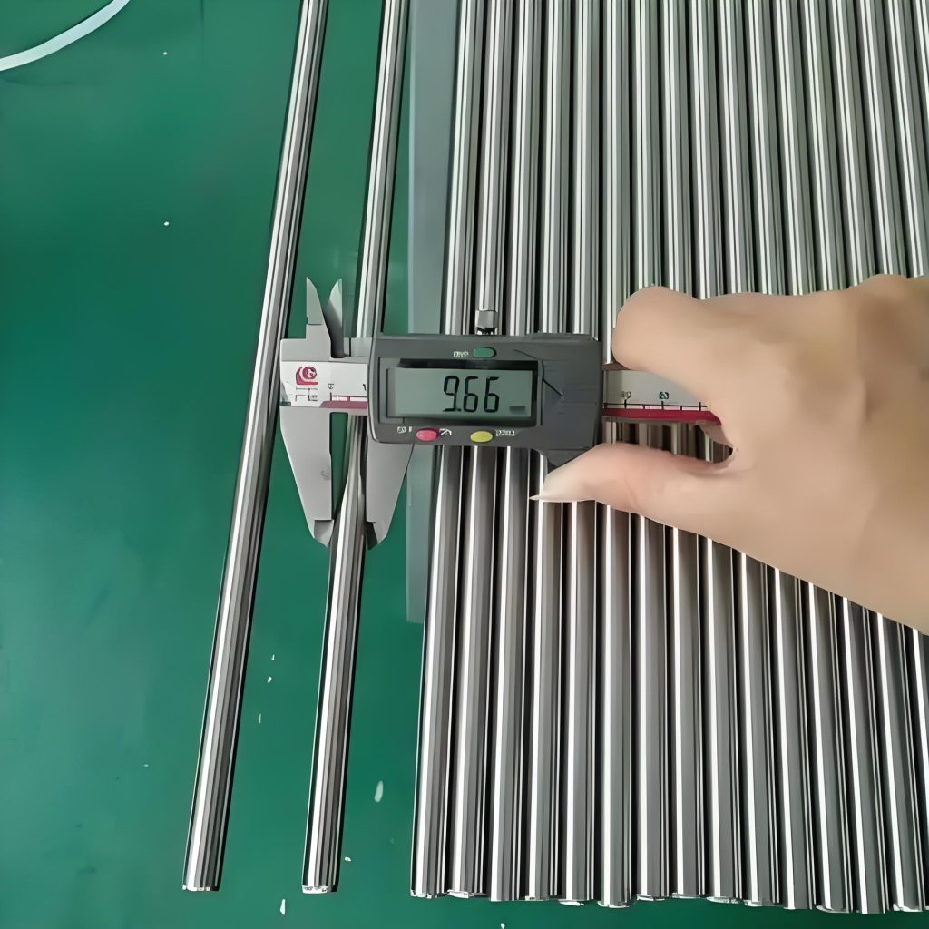
ASTM A269 316L Stainless Tube Inspection Report
December 15, 2018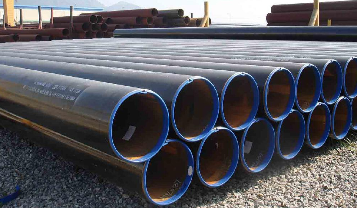
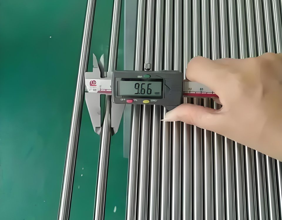
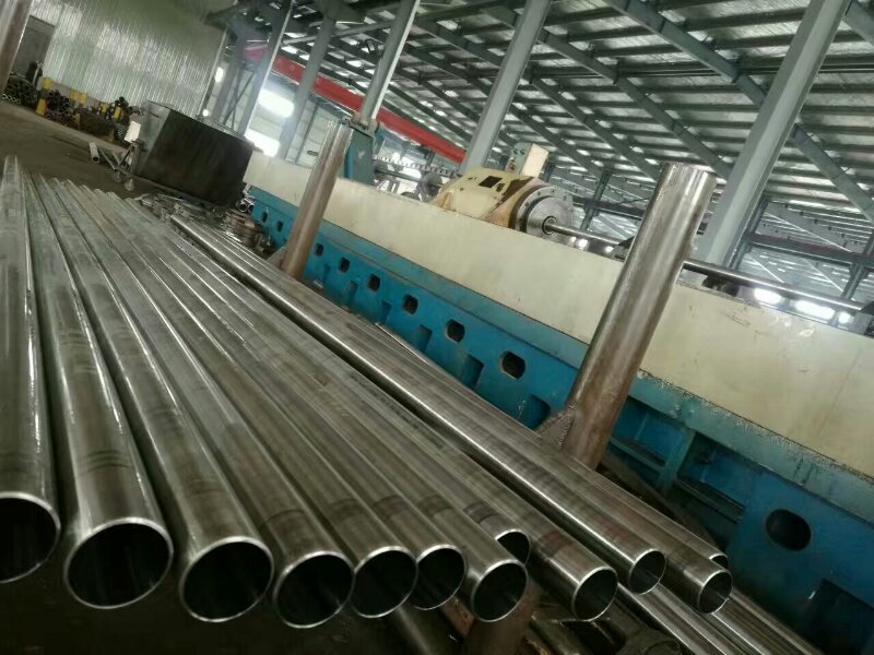
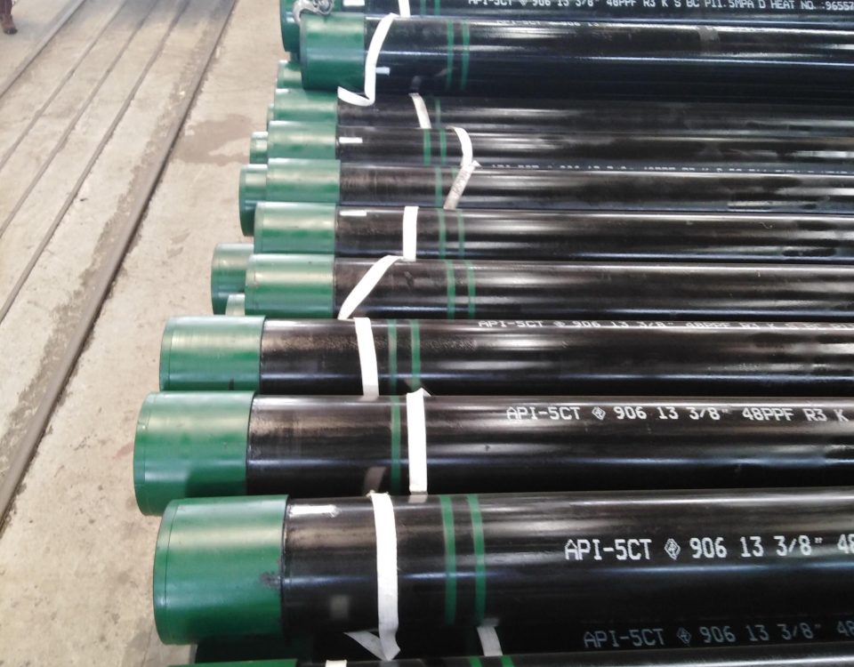
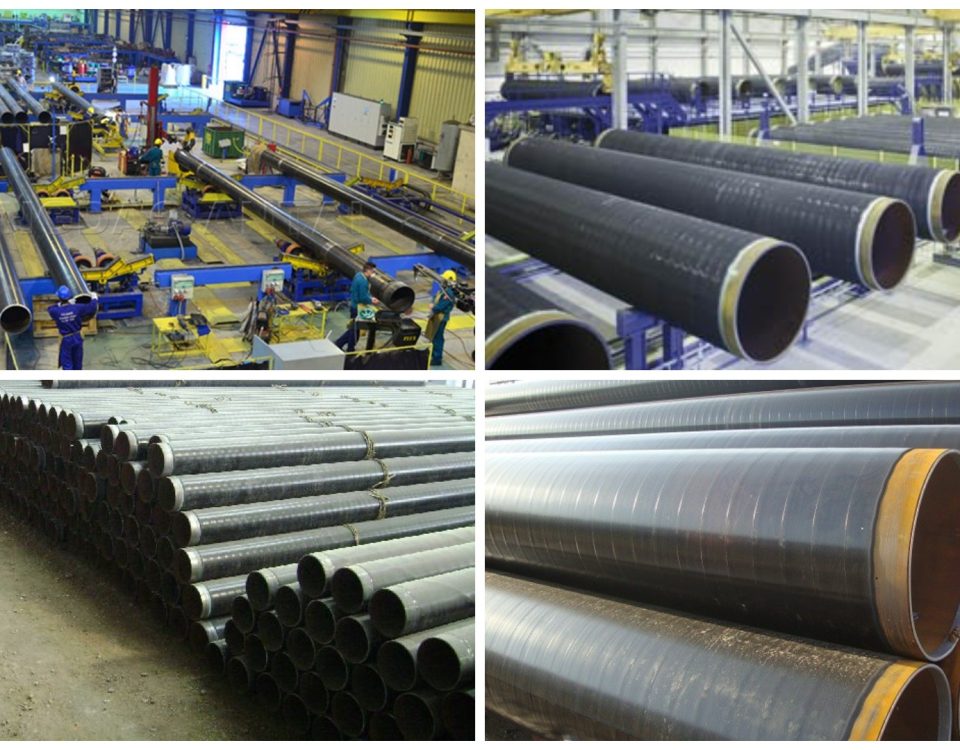
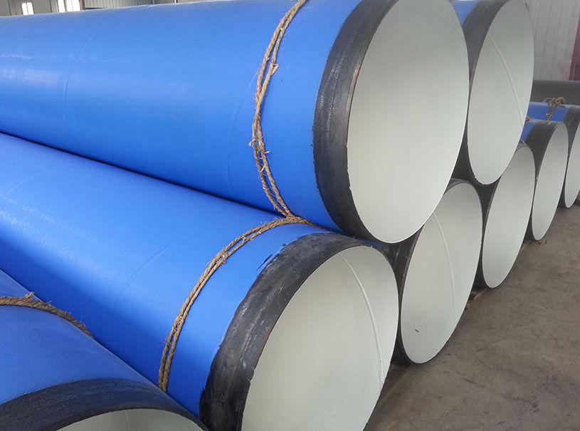
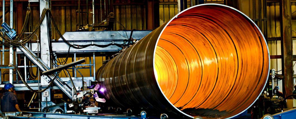
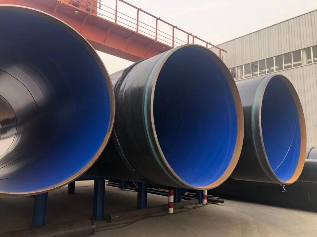
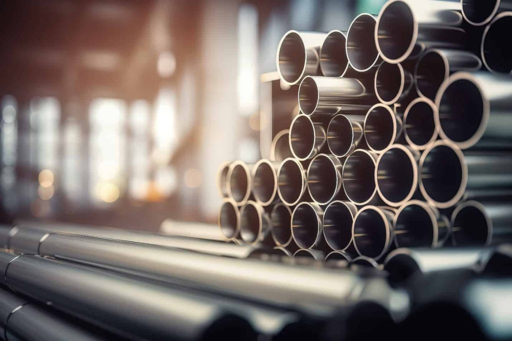
API 5L Grade-B ERW Line Pipe Technical Specifications , 20″DN (508.0 mm)×WT 7.9 mm
December 29, 2018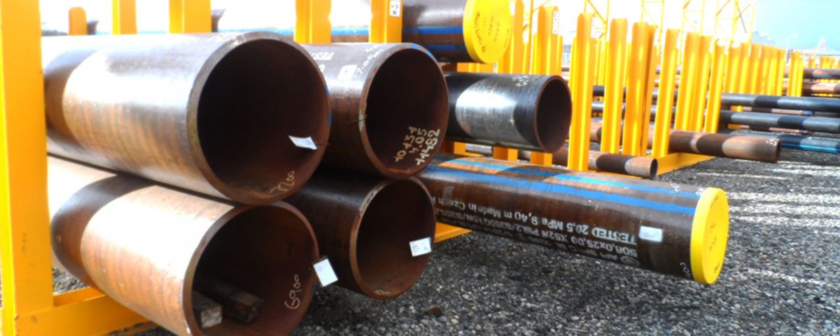
M. N. Ervina Efzan*, S. Kesahvanveraragu, J. Emerson
1.0 INTRODUCTION
1.1 Offshore Pipeline Material
Pipelines in offshore platform are made up of various types of materials. Selection of material relies upon certain considerations such as cost, functional requirement, operating conditions of pressure and temperature, corrosion rate and so forth [1-2]. Since there are varieties of pipelines in offshore platform, material selection and those considerations are highly required. In offshore industry, metal is the highly used material that can be assorted into ferrous and non-ferrous metals [1-3]. Metals containing iron (Fe) as their premier composition are known as ferrous metals, whereas metals containing other elements are termed as non-ferrous metals [4-5]. Cast iron and steels belong to ferrous metal category, whereas non-ferrous metals are inclusive of aluminium (Al), copper (Cu), tin (Sn) and silicon (Si) [3-5]. According to Mamdouh [6], ferrous metals are the mostly used metals to build offshore platform pipelines due to the cost effectiveness and capability of withstanding the
operating condition.
1.2 Plain Carbon Steel
Carbon steel is a material consisting of carbon as its main alloying element. Carbon steel is made up of iron (Fe), carbon (C), phosphorus (P), manganese (Mn), sulphur (S) and silicon (Si) [7]. Currently in the worldwide market, carbon steel is being manufactured and used in large quantities for heavy industries, especially offshore transport system and oil extraction [8]. This is because carbon steel has high strength, good weldability, high temperature resistance, good surface protection to the external environment and cheaper than other alloy steels such as low alloy steel and stainless steel [3-4].
Carbon steel can be classified into low, medium and high carbon steels based on its carbon content (Indian Institutes of Technology, 2010). Low carbon steel is also termed as mild steel and usually contains less than 0.3% carbon. Meanwhile, medium and high carbon steels have a carbon content of 0.3 – 0.45% and 0.45 – 0.75% respectively [4][9]. Pipeline industry especially offshore pipelines may not use medium and high carbon steel due to their poor resistance of brittleness and reduction of weldability [10]. Hence, low carbon steel is preferable in offshore pipelines among designers, fabricators and regulators. It covers the pipeline network of high temperature vessels, heat exchangers, compressors and transmission pipelines [9][10]. Detailed information on the utilization of low carbon steels in offshore processing platform pipelines is tabulated in Table 1. From Table 1, low carbon steel Type API 5L Grade X52 has the highest tensile strength of 455 MPa, whereas Type API 5L Grade B possesses the lowest tensile strength of 413 MPa.
Table 1: Types of low carbon steels in offshore processing platform according to codes and standards, tensile strength, material composition and applications:
|
No. |
Codes and Standard (ASTM/API) |
Tensile Strength (MPa) |
Composition of Materials |
Applications in Offshore Platform |
Reference |
|
1 |
A106 Grade B (Seamless Pipe) |
415 |
C <= 0.30 Mn <= 1.06 P <= 0.035 S <= 0.035 |
1. Seawater system 2. Water injection system 3. Produced water system 4. Portable water system 5. Dry fuel and gas system 6. Fire water system 7. Glycol and methanol injection system 8. Inert gas/plant air piping |
[2] [11] [12] |
|
2 |
API 5L Grade B (Welded Pipe) |
413 |
C <= 0.28 Mn <= 1.20 P <= 0.030 S <= 0.030 |
[2] [11] [13] |
|
|
3 |
A671 Grade CC60 (Welded Pipe) |
415 |
C <= 0.21 Mn <= 0.98 P <= 0.035 S <= 0.035 |
[2] [11] [14] |
|
|
4 |
API 5L Grade X52 (Seamless Pipe) |
455 |
C <= 0.28 Mn <= 1.40 P <= 0.030 S <= 0.030 |
[2] [11] [13] |
|
|
5 |
A333 Grade 6 (Seamless Pipe) |
415 |
C <= 0.30 Mn <= 1.06 P <= 0.025 S <= 0.025 |
1. Flare system 2. Seawater system 3. Fire water system 4. Drain and sewage system |
[2] [11] [15] |
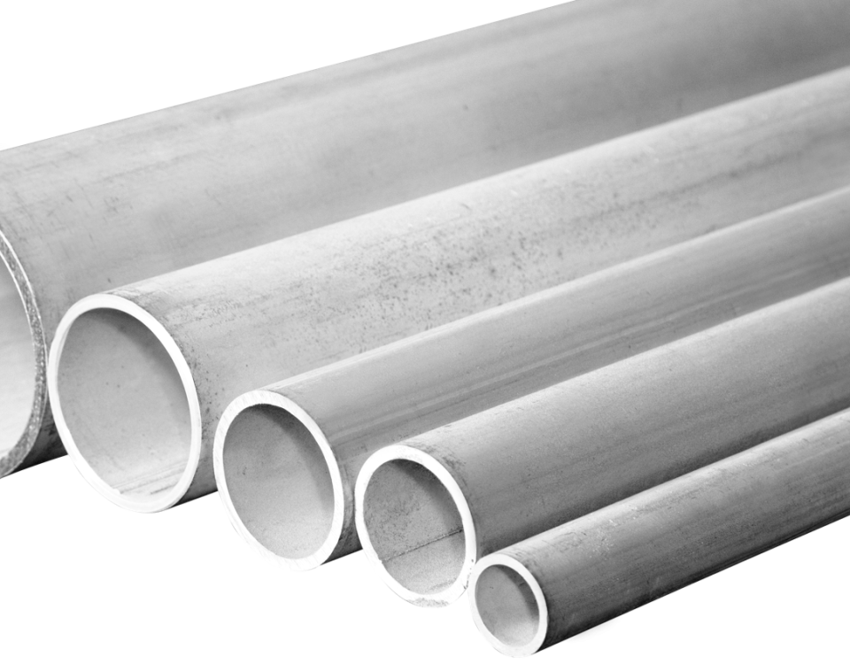
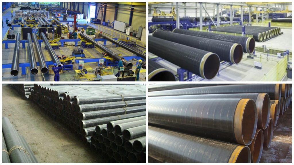
1.3 A333 Grade 6 Low Carbon Steel Pipe
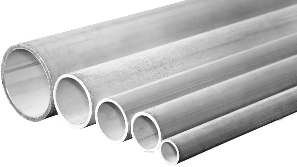
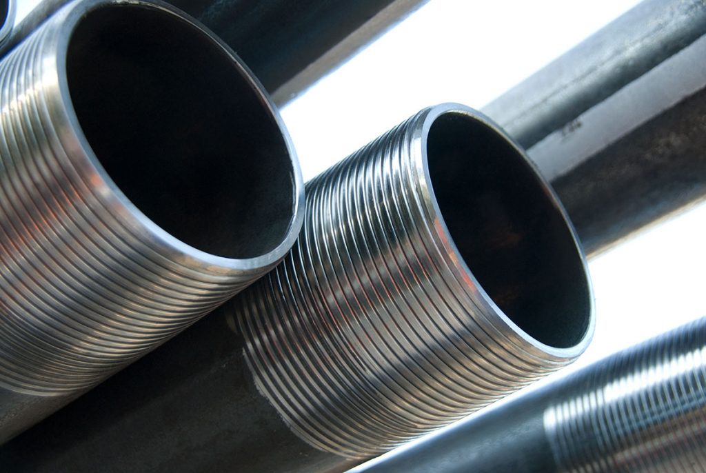
Based on the comprehensive data in Table 1, material type A333 Grade 6 was chosen to analyse the microstructure characterization
and mechanical properties of the material. In general, A333 Grade 6 pipe is called as a low temperature pipe since it may withstand
impact toughness at temperature as low as -45°C [15].
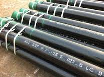
Figure 1 shows the samples of A333 Grade 6 low carbon steel pipes.
2.0 METHODOLOGY
2.1 Microstructural Characterization
According to Sharmila [17], the magnified image is essential to investigate the morphology, microstructure, and shape of various features including grains, phases and embedded particles. Currently, there are various microscopy methods widely used in research field such as optical microscopy (OM), scanning electron microscopy (SEM) and transmission electron microscopy (TEM). According to Grubb [18], there are various advantages of using an optical microscope such as captures images with high resolution, fast data acquisition and provides more quantitative results. Hence, light microscopy method was used to characterize the microstructure of A333 Grade 6 material.
Optical microscopy needs the specimen’s surface to be flat, smooth and scratch free.
However, it does not need not to be in any specific shape such as rectangular, circular or other geometries. As such, a proper sample preparation was done before conducting the microstructure characterization through optical microscopy. A333 Grade 6 low carbon steel pipe sample was cut into 1 cm length, and the scrap metal sheet attached to the sample was removed through grinding process. After cutting of sample, the surface was grinded to remove the rough surface and scratches on the sample. Furthermore, two different polishing solutions such as polycrystalline diamond (3 µm and 1 µm) and non-crystalline colloidal silica were poured evenly on the test pans to ensure an effective polishing process. A reflective surface was attained after completion of polishing process.
Etching is the final step of sample preparation prior to observation of microstructure via optical microscope. Etching is used to mean the physical and chemical peeling of atomic layers of a material [17]. According to Niaz [19], nital is the best etching solution for low carbon steels [20]. Moreover, etching time is an important factor to be considered in order to ensure the sample surface etched up to the exact level. Generally, low carbon steels need to be etched using nital in time frame from seconds to minutes [21]. A333 Grade 6 low carbon steel sample was etched for 3 min to ensure precise display of microstructure. Figure 2 displays the etching process of A333 Grade 6 low carbon steel sample surface.
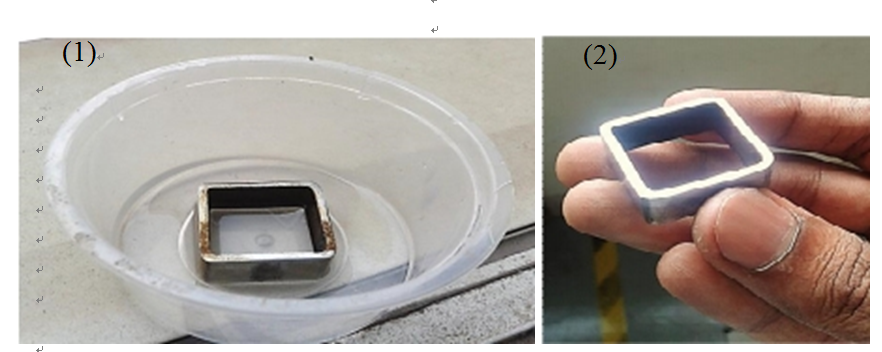
Figure 2: (1) Etching Process; (2) After Etching and Cleaning Process
After sample preparation had been completed precisely, microstructure of the material surface was observed through optical microscope under three different optical magnifications, namely 10X, 20X and 50X.
2.2 Vickers Hardness Test
The prepared specimen was mounted on the anvil of Vickers tester device under microscopic view. 10 kgf load was then applied and followed by pressing of diamond pyramid into the flat surface of the specimen for a duration of 15 s. After completion of dwelling time, the dent was observed through microscopic view. The size of the dent needs to be calculated by measuring the two diagonals [22].
3.0 RESULTS AND DISCUSSION
3.1 Microstructural Characterization
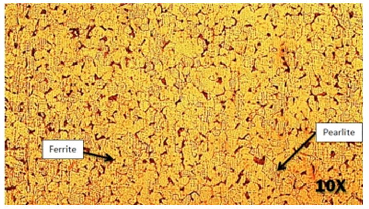
Figure 3: Microstructure of A333 Grade 6 Low Carbon Steel under magnification of 10X. Pearlite and ferrite layers are labelled to differentiate the phase structure.
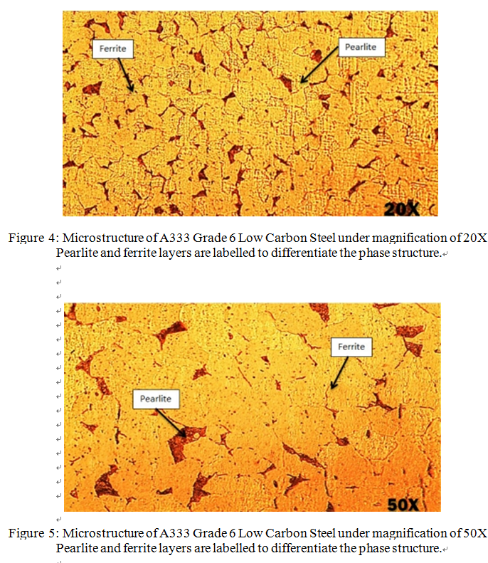
From the results of light microscopy, microstructures of the sample surface under magnification of 10X, 20X and 50X are illustrated in Figures 3, 4 and 5 respectively.
According to Scott [23], low carbon steel has two major constituents, which are pearlite and ferrite. Pearlite is defined as dark regions in the microstructure, and it consists of fine blend of ferrite and iron carbide particles. Meanwhile, according to Koo [24], pearlite grains are found lying along the ferrite grain boundaries. On the other hand, the brighter regions are known as ferrite, and the grain boundaries between the ferrite particles are clearly visible. In general, low carbon with 0.16% carbon content consists of volume fraction, 0.79% proeutectoid ferrite and 0.21% of pearlite respectively [24]. Both pearlite and ferrite layers are labelled in Figures 3, 4 and 5. In addition, microstructures under magnification of 10X and 20X display clear grain boundaries in between the ferrite grains. Figure 6 shows a shape of ferrite in low carbon steel to justify the statement regarding grain boundaries in ferrite grain.
Figure 6: Grain boundary allotriomorphic in low carbon steel [23]
The importance of analysing the microstructure of a material, especially steels or alloys, is to determine the properties of the material by observing the particle size and amount in the material itself. Based on Hall-Petch relationship, the reduction of grain size improvises the strength of steel [25]. Similarly, from the results obtained through optical microscope, low carbon steel Type A333 Grade 6 is made up of smaller size of ferrite grain boundaries.
3.2 Vickers Hardness Test
According to the data generated from Section 2.2, Vickers hardness test results depend on the applied load, dwelling duration and indention diameters. Hence, for this test, 10 kgf was applied for 15 s to indent on the A333 Grade 6 low carbon steel specimen. The test was repeated on 5 different regions of the specimen, which include 4 edges and a midpoint of the sample. Once the Vickers indenter made a pit on the specimen in a form of the diamond shape pyramid, the filler lines were adjusted to the both edges of diagonals, and the values were recorded in the device. Then, the results were displayed in terms of HV, which shows the hardness level provided by Vickers hardness tester. The obtained results include diagonal diameters and hardness values for 5 points, and the average HV for the sample is demonstrated in Table 2.
Table 2: Hardness Value of the Sample A333 Grade 6 Low Carbon Steel
|
Low Carbon Steel: A333 Grade 6 (20 mm x 10 mm x 2 mm) Rectangular Specimen |
|||
|
Point |
Diameter 1 (µm) |
Diameter 2 (µm) |
Vickers Hardness (HV) |
|
1 |
330.075 |
332.100 |
169.131 |
|
2 |
336.960 |
340.605 |
161.535 |
|
3 |
336.555 |
333.315 |
165.268 |
|
4 |
329.670 |
326.835 |
172.065 |
|
5 |
328.455 |
333.720 |
169.131 |
|
Average Vickers Hardness Value |
166.826 |
||
The results obtained were verified by the microstructure of the indentation through optical microscopy. Figure 7 depicts the microstructure sample of the diamond shaped indentation on Point 1, 3 and 5 of the specimen respectively.
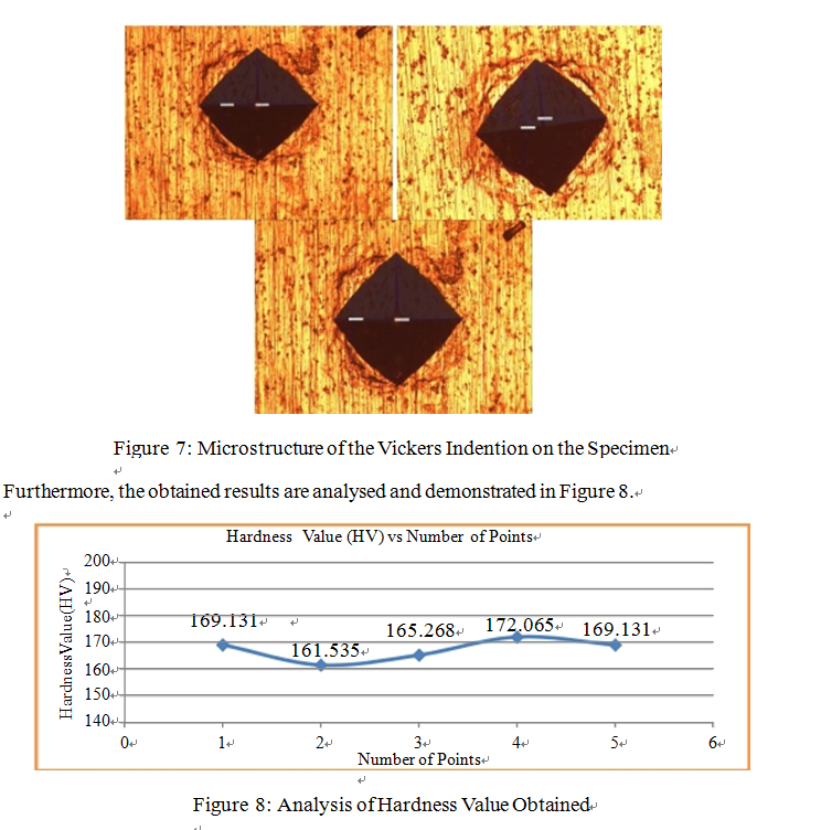
It shows that there is a slight difference among the results of Hardness Value (HV). Although the test was done on 5 different points, the hardness values obtained should be identical due to the same tested material. According to Tanaka and Kamiya [22], surface roughness influences the measurement of hardness value. Although the specimen surface was grinded evenly, there was deterioration in the result accuracy. Nevertheless, according to Samuels [26], the hardness level of low carbon steel (0.1% carbon content) is 140HV. Meanwhile, the results obtained for A333 Grade 6 low carbon steel show that the hardness value is about 166.826HV.
4.0 CONCLUSION
Overall, it can be concluded that A333 Grade 6 low carbon steel possesses microstructure with smaller grain size and less pearlite content. This information has validated the high strength and ductility of the material. Meantime, hardness mean value of this material is 166.836HV, and it complies of the range of hardness value for oil and gas pipelines, which is the maximum of 250HV. Since A333 Grade 6 low carbon steel has appropriate crystal structure and hardness level, it is suitable to be used as an offshore platform pipeline material.
Moreover, the outcome of this paper could contribute to further research on offshore pipeline material.
REFERENCES
[1]M.Tanzosh,Chapter A3: Piping Materials, in Piping Handbook, New York, McGraw-Hill, (2000).
[2]M.Tanzosh,Chapter A3: Piping Materials, in Piping Handbook, New York, McGraw-Hill, (2000).
[3]Norsok Standard, M-001 Material Selection, Norwegian Petroleum Industry, Norway,(2004).
[4]Papavinasam,Chapter 3 – Materials, Corrosion Control in the Oil and Gas Industry, (2014) 133-177.
[5]F.Ashby,Materials Selection in Mechanical Design, Burlington: Elsevier Publisher, (2005).
[6]Lyons,5 – Ferrous and non-ferrous metals, Materials for Architects and Builders, 3 (2006) 149-196. Subrata, Handbook of Offshore Engineering, Plainfield: Elsevier Ltd. (2005).
[7]H.S. Wenyong Wu, Microstructure, mechanical properties and corrosion behavior of laser welded dissimilar joints
between ferritic stainless steel and carbon steel, Materials & Design, 65 (2014) 855-861.
[8]Stipanicev,F. Turcu, L. Esnault, O. Rosas, R. Basseguy, M. Sztyler, I.B. Beech, Corrosion of carbon steel by bacteria
from North Sea offshore seawater injection systems: Laboratory investigation, Bioelectrochemistry 97 (2013) 76-88.
[9]Smith,Piping Materials Selection and Applications, Burlington: Gulf Professional Publishing, (2005).
[10] A.J. Bryhan, W. Troyer, Weldability of a Low Carbon Mo-Nb X-70 Pipeline Steel, Welding Research, 1 (1980) 37-47.
[11] Norsok Standard, Material Data Sheets for Piping, Ed 6, Norwegian Petroleum Industry, Norway (2013).
[12] American Piping Products, Product Catalog, Available: http://www.amerpipe.com/products. (2014).
[13] Guangdong Lizz Steel Pipe Co., Ltd, APE Spec 5L Gr.B Carbon Steel Piping, Available: http://www.apisteel.com/api-spec-5l-gr-b-carbon-steel-piping-1611/. (2014)
[14] Aesteiron Steels Private Limited, ASTM A671 EFW Pipes, https://www.abtersteel.com/. (2014).
[15] American Society for Testing and Materials (ASTM), ASTM A333: Standard Specification for Seamless and Welded Steel Pipe for Low Temperature Service, American Society for Testing and Materials (ASTM), Washington, (2013).
[16] Sunny Steel Enterprise Ltd., ASTM A333 Grade 6 Seamless Pipe, Sunny Steel Enterprise Ltd., 2011. Available: http://www.sunnysteel.com/astm-a333-grade-6_seamless-pipe.php#.VDBllXkcT6U. (2014).
[17] S. M. Mukhopadhyay, Sample preparation for microscopic and spectroscopic characterization of solid surfaces and films,
Sample preparation techniques in analytical chemistry 162 (2003) 377-411.
[18] D. Grubb, 2.17 – Optical Microscopy, Polymer Science: A Comprehensive Reference, 2 (2012) 465-478.
[19] F. Niaz, M. R. Khan, I. Haque, “Microstructural characterization of low carbon steel used in aircraft industry, JPMS Conference Issue, Pakistan, (2010).
[20] P.G. Ulyanov, D.Yu. Usachov, A.V. Fedorov, A.S. Bondarenko, B.V. Senkovskiy, O.F. Vyvenko, S.V. Pushko, K.S. Balizh, A.A. Maltcev, K.I.
Borygina, A.M. Dobrotvorskii, V.K. Adamchuk, Microscopy of carbon steels: Combined AFM and EBSD study, Applied Surface Science 267 (2013) 216-218.
[21] E. Girault, P. Jacques, Ph. Harlet, K. Mols, J. Van Humbeeck, E. Aernoudt, F. Delannay, Metallographic Methods for
Revealing the Multiphase Microstructure of TRIP-Assisted Steels, Materials Characterization 40 (1998) 111-118.
[22] M.A.H. Kamiya, Analysis of the grinding of toner sheets using Vickers hardness as an index of grindability, Powder Technology 164 (2006) 82-88.
[23] D.A. Scott, Metallography and Microstructure of Ancient and Historic Metals, Singapore: The J. Paul Getty Trust (1991).
[24] K.M. Koo, M.Y. Yau, Dickon H.L. Ng, C.C.H. Lo, Characterization of pearlite grains in plain carbon steel by Barkhausen emission,
Materials Science and Engineering: A, 351 (2003) 310-315.
[25] Pauli Lehto, Heikki Remes, Tapio Saukkonen, Hannu Hänninen, Jani Romanoff, Influence of grain size distribution on the Hall–Petch relationship of welded structural steel, Materials Science and Engineering 592 (2013) 28-39.
[26] L. E. Samuels, Light Microscopy of Carbon Steels, United States: ASM International, 1999.