Properties of Galvanized Steel Pipe Welds
January 4, 2019
Corrosion Resistance of API 5L Pipeline Steel with Coating Protection
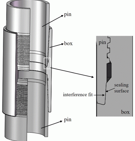
January 7, 2019In recent years, with the decreasing number of easily exploitable oil and gas wells, it has become necessary for oil and gas wells to go deeper on both underground and underwater. And, tubing and casing strings are subjected to higher temperature and higher pressure in these wells, which would probably cause casing failure or gas leakage in the high-pressure/high-temperature (HPHT) wells. Hence, more attention has been paid to wellbore integrity in oil and gas industry in recent years.1,2 The key factor of wellbore integrity is casing string connections, which are expected to provide both structural and leakage integrity under severe environment. As loading conditions are associated with deeper, higher temperature and pressure gas wells, many operators switched from using standard American Petroleum Institute (API) connections to the premium connections.Figure 1 shows the casing of premium connections and its gas sealing mechanism. The sealing surface is also called metal-to-metal seals, which provide contact pressure through the interference fit. What is more, the contact pressure on the sealing surface is higher than the gas well pressure, and the casing connections could prevent the gas leakage efficiently.3,4
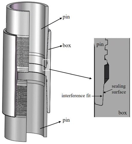
Figure 1. Gas sealing mechanism of premium connection.
In recent years, the gas sealing connection failed in some extra-high temperature gas well, although the designing contact pressure on the sealing surface was higher than the gas pressure. In the South China Sea, the temperature in some exploratory gas wells can reach up to 240°C.5 The well-designed premium connections could bear high-pressure gas in the downhole at early stage. However, the gas leakage problem could be detected after 2 years of gas production in some wells, which is far less than the expected service life of gas wells. At the extra-high temperatures, the sealing surface of casing connections will experience creep strain, which will lead to the reduction in the sealing surface’s contact pressure. When the contact pressure is lower than the gas well pressure, the gas will leak from the casing connection, which will reduce the service life of the gas well. Furthermore, it would bring a sustained casing gas pressure, casing collapse, or abandonment well, causing a huge economic loss. Therefore, it is significant to study the viscoelasticity of the casing connection’s material and find out the relaxation of contact pressure on sealing surface, which could be helpful for the exploration and development of high-temperature gas wells.
Research studies on the casing connections have been mainly focused on the thread connection structure design and safety evaluation in the past years. Analytical method,6,7 finite element (FE) method,8,9 and experimental method10,11 were commonly adopted in the research works. Some researchers have investigated the sealing mechanism of the premium connections,12,13 and some researchers developed high-performance premium connection in the high-temperature/high-pressure (HTHP) gas well.14,15However, these research works are all conducted in the steady state, not considering the time changing. And, the sealing mechanism of the premium connections in the high-temperature gas well has not been completely investigated, especially the viscoelastic behavior of the casing material.
In this article, a creep experiment of casing material was conducted under the same tension stress but different temperatures. And then, the viscoelastic behavior of the casing material is studied. Furthermore, the WLF (William–Landel–Ferry) equation for the casing material is derived. Finally, a FE model is used to study the relaxation of sealing surface’s contact pressure of the casing connection, which can predict its service life in the high-temperature gas well.
Experimental material tests
Experimental apparatus and procedure
According to ISO 204:2009, metallic materials’ uniaxial creep testing in tension method of test, creep experiments are performed under different high temperatures to estimate the material relaxation mechanical property based on the theory of viscoelasticity.16 As shown in Figure 2, the creep experiment apparatus is composed of oven, temperature sensor, displacement senor, tension tester, and specimen. The experiment principle is shown in Figure 2(b). The bottom of specimen is fixed, and the top is loaded. Experimental temperature is controlled by oven and temperature sensor. Meanwhile, the creep strain is recorded by displacement sensor. The specimen casing material is P110T and its chemical composition is listed in Table 1. As the metal creep experiment is time-consuming, a set of constant tension load tests are carried out at 120°C, 200°C, and 300°C, respectively.
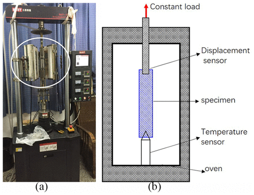
Figure 2. (a) Creep experiment apparatus and (b) experimental principle.
Experimental result
Table 2 shows the creep experimental conditions, which include a constant tension load of 680 MPa, three different temperatures, and consuming experimental time. Moreover, the loaded tensile stress is under the elastic limit of the P110T material. In test #1, the specimen was broken after 570 h experiment under 300°C, as shown in Figure 3. It shows that the fracture of specimen belongs to the necking phenomena. However, at a lower temperature and after 630 h of creep testing, the specimen did not fracture. It proves that the material creep behavior at 300°C is more obvious than at lower temperatures. The creep experiment results are shown in Figure 4. The strain–time curve at the 300°C consists of the whole three creep stages: primary, secondary, and tertiary. And, the strain rate is defined as the ratio of strain to the time. In the primary stage, the strain rate is relatively high, but slows with time. Then, the strain rate eventually reaches a minimum value and becomes a constant at the secondary stage, as the strain–time curve is a straight line at this stage. Finally, in the tertiary stage, the strain rate exponentially increases with time until the specimen fractures, which is mainly caused by necking phenomena in the specimen. However, for the specimen at 120°C and 200°C creep experiment, there were only two stages during the 630 testing hours: primary stage and secondary stage.
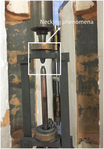
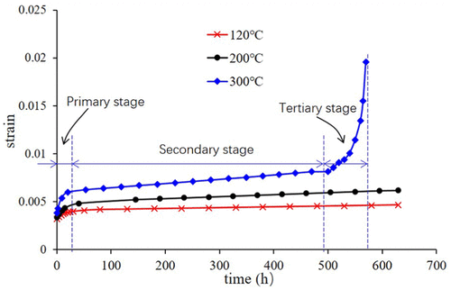
Figure 4. Creep experiment results under different temperature.
Viscoelastic constitutive model
In this article, the casing material is selected as linear viscoelastic. The constitutive relations can be expressed by the linear viscoelasticity superposition principle and the use of the relaxation and the creep modulus function.17,18 Starting from the generalized Maxwell model and adding one more spring term leads to a model known as Wiechert model, according to Figure 5. Using the Wiechert model, the creep and relaxation of viscoelastic material could be described well, and this model could be represented by the relaxation modulus function E(t) as follows
|
E(t)=E∞+∑i=1nEiexp(−tτi)E(t)=E∞+∑i=1nEiexp(−tτi)
|
(1) |
where τiτi is the relaxation time, EiEi is the relaxation modulus, E∞E∞ is the equilibrium modulus, and n is the total number of Prony series terms. Equation (1) represents the sum of a series of exponential terms and could be interpreted as a mechanical element model, also known as Prony series.
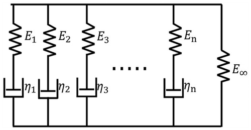
Figure 5. Wiechert material mode.
Note that, from equation (1), if t = 0
|
E(0)=E0=E∞+∑EiE(0)=E0=E∞+∑Ei
|
(2) |
where E0 is instantaneous relaxation modulus. And, equation (1) can be rewritten as follows
|
E(t)=E∞+∑i=1nmiE0exp(−tτi)E(t)=E∞+∑i=1nmiE0exp(−tτi)
|
(3) |
where mi=Ei/E0mi=Ei/E0 is defined as Prony series parameter.
P110T material characterization
As for the creep experiment, the application tension load is a constant, and the relaxation modulus can be represented by another form
|
E(t)=σ[ε]E(t)=σ[ε]
|
(4) |
where σσ is the application tension load; [ε][ε] is a strain matrix for the creep experiment, [ε1,ε2,ε3,…][ε1,ε2,ε3,…], corresponding to the experiment time matrix [t][t] or [t1,t2,t3,…][t1,t2,t3,…]. So the relaxation modulus E(t) in the matrix form is
|
E(t)=E0+∑i=1nmiE0[1−exp([t]τi)]E(t)=E0+∑i=1nmiE0[1−exp([t]τi)]
|
(5) |
Combining equation (4) with equation (5), the relationship between the time and the strain is established, as shown in equation (6)
|
∑i=1nmiE0[1−exp(−[t]τi)]=E0−σ[ε]∑i=1nmiE0[1−exp(−[t]τi)]=E0−σ[ε]
|
(6) |
By solving equation (6) by the method of linear matrix equation and substituting the time matrix [t][t] and the strain matrix [ε][ε] using the creep experimental data, the Prony series parameter mi can be obtained.
As for the computing complexity of the Prony series function, the MATLAB software is applied to find the Prony series parameter. For the 200°C environmental temperature, the Prony series parameter of the P110T casing material is listed in Table 3, and its relaxation modulus equation can be obtained as follows
|
E(t)=79,827+61,991[1−e−t10]+7367[1−e−t100]+49,615[1−e−t1000]E(t)=79,827+61,991[1−e−t10]+7367[1−e−t100]+49,615[1−e−t1000]
|
According to the Hooke law theory, the creep strain is the ratio of the constant tension stress to the relaxation modulus E(t). Moreover, the relationship curve of the creep strain versus time is plotted in Figure 6. Compared with strain–time curve in the experiment result at 200°C, as shown in Figure 6, the Prony series model curve fits well with the creep experimental data, which validate the constitutive model of the P110T material. Therefore, the Prony series equation of the casing material P110T at 120°C and 300°C can be also derived in the same way, as shown in equations (8) and (9), respectively
|
E(t)=125,986+875[1−e−t]+43,314[1−e−t12]+2956[1−e−t100]+38,942[1−e−t1000]E(t)=125,986+875[1−e−t]+43,314[1−e−t12]+2956[1−e−t100]+38,942[1−e−t1000]
|
(8) |
|
E(t)=53,560+66,362[1−e−t5]+6985[1−e−t10]+4802[1−e−t200]+30,015[1−e−t800]E(t)=53,560+66,362[1−e−t5]+6985[1−e−t10]+4802[1−e−t200]+30,015[1−e−t800]
|
(9) |
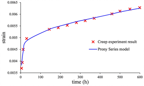
Figure 6. Creep experimental data and Prony series tensile versus at 200°C.
Thermo-rheological behavior of casing material
The relaxation modulus is temperature dependent.19,20 At lower temperatures, the material’s relaxation rate is very slow, which can be modeled as elastic behavior. At higher temperatures, the material’s relaxation rate becomes much faster, which is the pure viscous behavior. The relaxation modulus, obtained by the Prony series method, is plotted on a log time scale under the three different temperatures, as shown in Figure 7. It can be found that all the plots have almost the same shape but are only shifted horizontally. This is a property of the casing material and is called thermo-rheological behavior. The average of horizontal distance between two curves, at the top, middle, and bottom, is defined as shift factor, αTαT, and the relationship between the curves can be described by the following equation
|
E(log(t),T)=E(log(t)−logαT,T1)E(log(t),T)=E(log(t)−logαT,T1)
|
(10) |
where E(t, T) is the relaxation modulus at temperature T and time t.
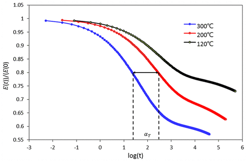
Figure 7. Thermo-rheological behavior of casing material P110T.
Equation (10) can be rewritten as follows
|
E(t,T)=E(tαT,T1)E(t,T)=E(tαT,T1)
|
(11) |
The shift factor αTαT can be obtained by the WLF equation
|
logαT=−C1(T−T0)C2+(T−T0)logαT=−C1(T−T0)C2+(T−T0)
|
(12) |
where T is the temperature at which the relaxation modulus is calculated, T0T0 is the reference temperature. C1 and C2 are constants of the WLF equation.
Based on the creep experimental data and Prony series method in Figure 6, and setting 200°C as the reference temperature, the shift factors, from 200°C to 120°C and 200°C to 300°C, can be scaled in the plot. By substituting the shift factors in the WLF equation, the constants C1 and C2 can be solved: C1 = 45.03 and C2 = 4640. Therefore, the WLF equation for the casing material P110T is
|
logαT=−45.03(T−200)4640+(T−200)logαT=−45.03(T−200)4640+(T−200)
|
(13) |
FE simulation and its application
FE model
The numerical simulation of the specimen tension creep test was performed using the commercial FE software ABAQUS. Basing on the casing material P110T creep experiment loading, the FE mechanical model was established, as shown in Figure 8. The elastic properties, including elastic modulus and Poisson’s ratio, 1.99 × 10⁵ MPa and 0.3, respectively, are defined in ABAQUS. Besides, the viscous properties, including the relaxation time and Prony series, as shown in Table 3, are also defined in ABAQUS. What is more, the thermo-rheological simple (TRS) parameters, C1 and C2, obtained by the WLF equation, are also included in this simulation, and *VISCO type of analysis was applied for the viscoelastic behavior.

Figure 8. FE mechanical model used for simulation of the tension creep test.
The comparison between the creep experimental data and the simulation results at three different temperatures is shown in Figure 9(a)–(c), respectively. At temperature 200°C, the simulation result matches the creep experimental data well. This is because temperature 200°C was set as reference temperature in equation (13). But for the temperatures 120°C and 300°C, as thermo-rheological behavior, there are small differences between the experimental and the simulated results, and the biggest difference is less than 8%. The reason for this difference is because that, for the FE analysis, the thermo-rheological parameters are applied into the simulation, which is obtained from the WLF equation. In the WLF equation, the 200°C is taken as the reference temperature, so that, in Figure 7, the red curve is shifted to the position of the blue curve and black curve. And, the new shifted curves represent the thermo-rheological behavior of the casing material and is used to solve the WLF equation. Because the shifted curves cannot 100% match well with the original one, which is obtained by the experimental results, the deviation exists between experimental and simulation. Moreover, as the 200°C is taken as a reference temperature, the simulation result is more accurate than others, as shown in Figure 9. Therefore, the simulation results show the validity of the viscoelastic theory and TRs method in this article. In addition, the FE model can be used to estimate the viscoelastic behavior of casing material P110T at different mechanical and thermal conditions.

Figure 9. Comparison of experimental data and simulation result under different temperatures: (a) 120°C, (b) 200°C, and (c) 300°C.
Contact pressure on the sealing surface
Based on the geometry of 5.5″ SL-APOX joint connection type, an axial symmetry FE model for the sealing surface was built in ABAQUS, as shown in Figure 10. The inner wall is under the applied gas pressure. The red line in the figure represents the sealing surface. If the gas pressure is higher than the contact pressure on the sealing surface, the joint connection will be more likely to leak.
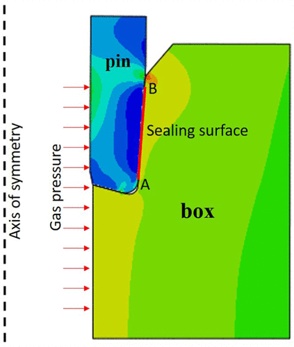
Figure 10. Finite element model of the sealing surface from the SL-APOX joint connection.
At high-temperature environment, the contact pressure on the sealing surface will decrease with time due to the material viscoelasticity. The gas pressure on the inner wall is set to 75 MPa. The simulation result of the averaged contact pressure relaxation on the sealing surface versus time is shown in Figure 11. Simulation results show that the initial average contact pressure is 116 MPa at 160°C and 230°C. Then, the average contact pressure decreases with time. The average contact pressure drops to 76 MPa. Furthermore, the rate of decreasing pressure at 230°C is faster than the one at 160°C environment. It is shown that within 4000 h (166 days), the contact pressure drops to 76 MPa at 230°C. However, at a lower temperature environment, it will take 9000 h (375 days) to drop to 76 MPa.
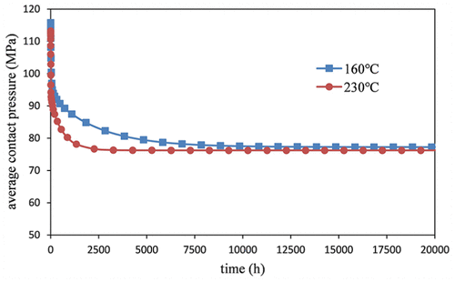
Figure 11. Relaxation of contact pressure on the sealing surface varying with time.
According to the simulation result, the ratio of the initial contact pressure and the finial contact pressure is 1.56, which means, at high-temperature environment, the final contact pressure on the sealing surface will drop by almost a third. Based on the safety factor equation
|
n=[σ]σgpn=[σ]σgp
|
(14) |
where n is the safety factor, [σ][σ] is the designing contact pressure, σgpσgp is the intending sealing gas pressure. The safety factor n must be more than 2 for the safety consideration.
Conclusion
-
The relaxation of the contact pressure on the sealing surface of the premium connection is the main reason for the gas leakage from the casing at high-temperature natural gas well.
-
At high temperatures, creep tension experiment was employed to study the viscoelastic behavior of the casing material P110T. The mechanical behavior of the casing material is strongly temperature dependent. The higher the temperature environment is, the faster the creep rate is.
-
The constitutive model for the casing material P110T was derived through creep experimental data, and the Prony series parameter was calculated. The thermo-rheological behavior was also investigated, and the shift factors of the material between environmental temperatures of 120°C to 300°C are obtained.
-
A viscoelastic FE model for the material P110T was established, and the simulation results fit well with the experimental data.
-
The FE model of a sealing surface in the premium connections was built in ABAQUS, and its contact pressure relaxation was investigated. It is recommended that the designing contact pressure on the sealing surface should be twice as much as the intending gas sealing pressure at high-temperature natural gas wells.
Handling Editor: Michal Kuciej
Declaration of conflicting interests
The author(s) declared no potential conflicts of interest with respect to the research, authorship, and/or publication of this article.
References
Teodoriu, C, Kosinowski, C, Amani, M. Wellbore integrity and cement failure at HPHT conditions. Int J Eng Appl Sci 2013; 2: 1–13.
Paul Cernocky, E, Valigura, GA, Scholibo, FC. A standardized approach to finite element analysis of casing-tubing connections to establish relative sealing performance as a function of design geometry, machining tolerances, and applied loads. In: Idelsohn, S, Oñate, E, Dvorkin, E (eds) Computational mechanics. Barcelona: CIMNE, 1988, pp.1–19.
Ong, G, Nizam Ramli, M, Ahmad, H. Evaluation of fatigue performance on semi premium connection for casing drilling application to prevent connection fatigue failure. In: Proceedings of the off shore technology conference Asia, Kuala Lumpur, Malaysia, 22–25 March 2016, https://www.onepetro.org/conference-paper/OTC-26807-MS
Sugino, M, Yamaguchi, S, Ugai, S., an innovative high-performance premium threaded connection for OCTG. Nippon Steel & Sumitomo Metal technical report no. 107, February 2015, pp.10–17, http://www.nssmc.com/en/tech/report/nssmc/pdf/107-03.pdf
Takano, J, Yamaguchi, M, Kunishige, H. Development of premium connection “KSBEAR” for withstanding high compression, high external pressure, and sever bending. Kawasaki Steel technical report no. 47, 2002, http://www.jfe-steel.co.jp/archives/en/ksc_giho/no.47/e47-014-022.pdf
Kim, J, Lee, HS, Kim, N. Determination of shear and bulk moduli of viscoelastic solids from the indirect tension creep test. J Eng Mech 2010; 136: 1067–1075. 3
Lopes, J, Alberto, C, Tomas, J. Viscoelastic relaxation modulus characterization using Prony series. Lat Am J Solids Stru 2015; 12: 420–445.
Park, SW, Schapery, RA. Methods of interconversion between linear viscoelastic material functions. Part I—a numerical method based on Prony series. Int J Solids Struct 1999; 26: 1653–1675.
Ananthasayanam, B. Computional modeling of precision molding of aspheric glass optics. All Dissertations 326, 2008, http://tigerprints.clemson.edu/all_dissertations/326

