
How does the casing pipe work ? Choose your casing tubing !
January 9, 2018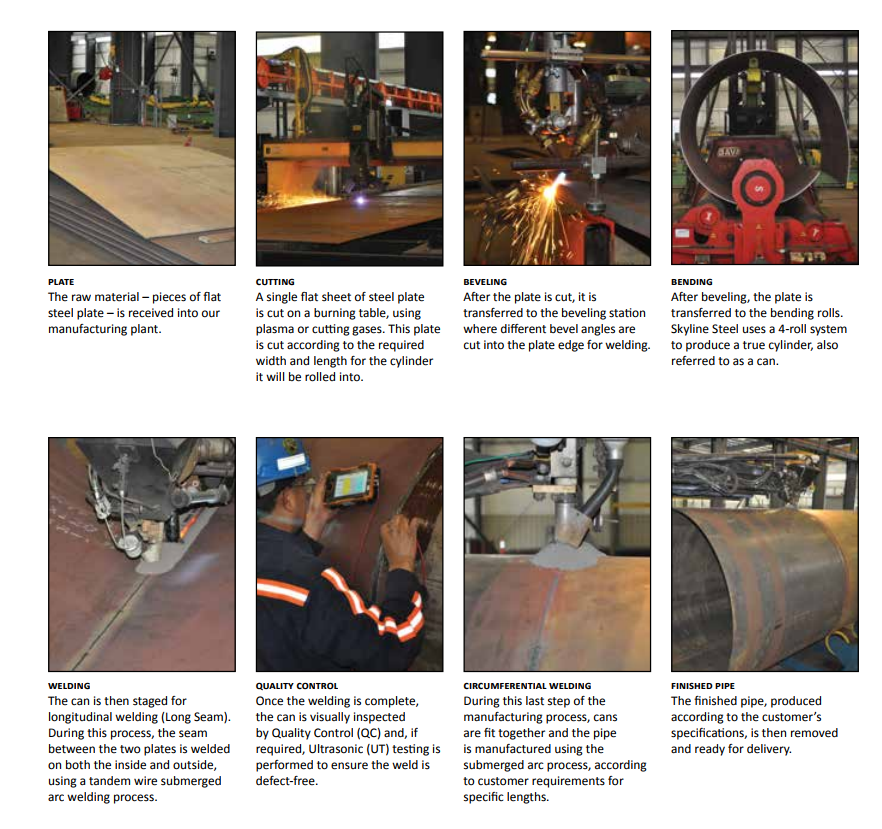
ERW ,Spiral weld Pipe Definition and Manufacturing Process
January 21, 2018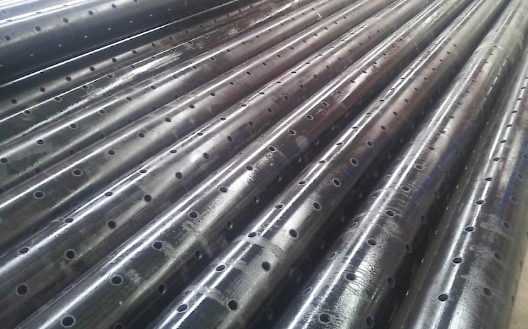
Casing pipe definition:
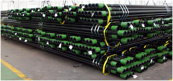
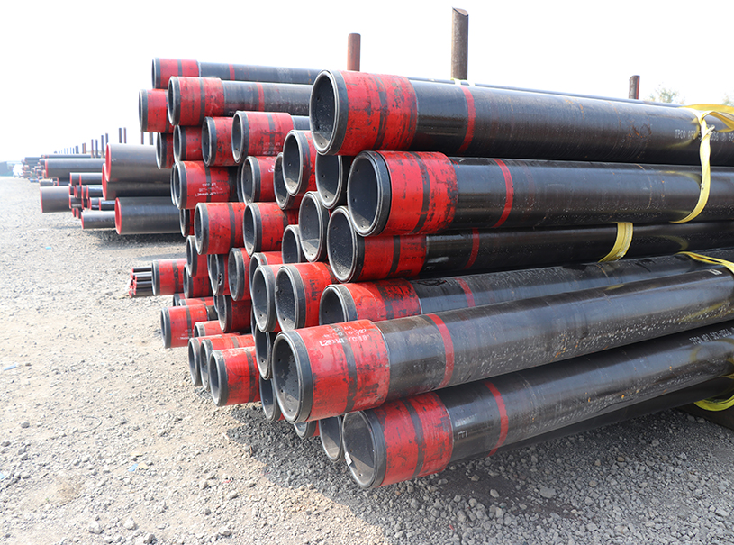
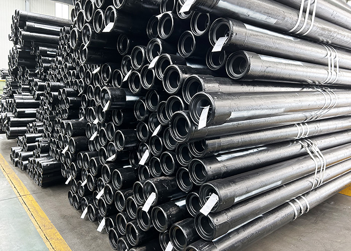
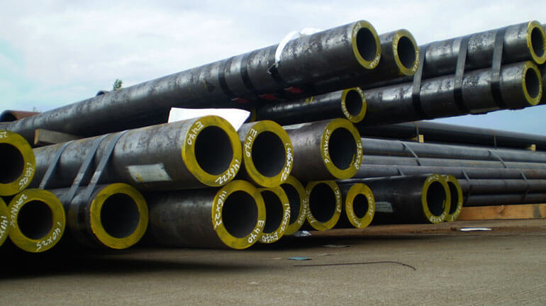
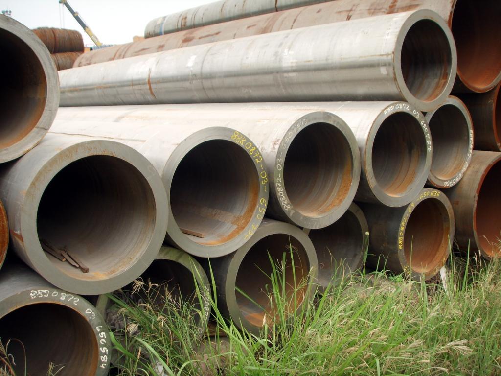
Casing is a series of steel pipes that are run into a drilled oil well to stabilize the well, keep contaminants and water out of the oil stream, and prevent oil from leaching into the groundwater. Casing is installed in layers, in sections of decreasing diameter that are joined together to form casing strings. The five types of casing string are conductor casing, surface casing, intermediate casing, casing liner, and production casing.
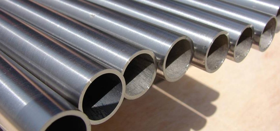
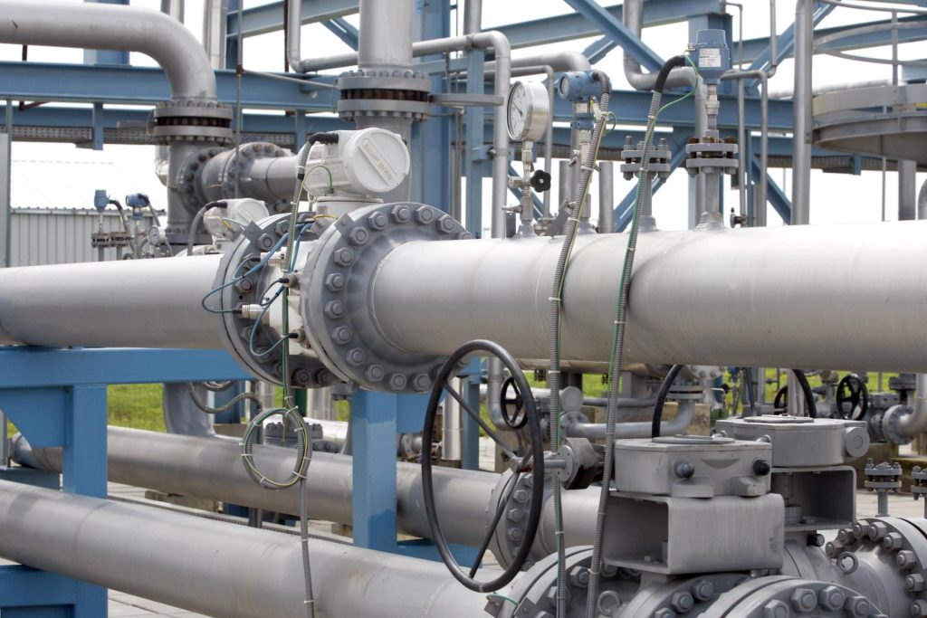
casing pipe: The outer tubes are called casing. Casing lines the wellbore and thus protects the layers of soil and above all the groundwater from being contaminated by the drilling mud and/or frac fluids. It also stabilizes the wellbore, so casing must be able to withstand especially high loads. The drilling and casing alternate – the drill string is taken out at specific intervals and the wellbore is lined with casing and cemented. Then drilling continues.
Steel pipe cemented in place during the construction process to stabilize the wellbore. The casing forms a major structural component of the wellbore and serves several important functions: preventing the formation wall from caving into the wellbore, isolating the different formations to prevent the flow or crossflow of formation fluid, and providing a means of maintaining control of formation fluids and pressure as the well is drilled. The casing string provides a means of securing surface pressure control equipment and downhole production equipment, such as the drilling blowout preventer (BOP) or production packer. Casing is available in a range of sizes and material grades.
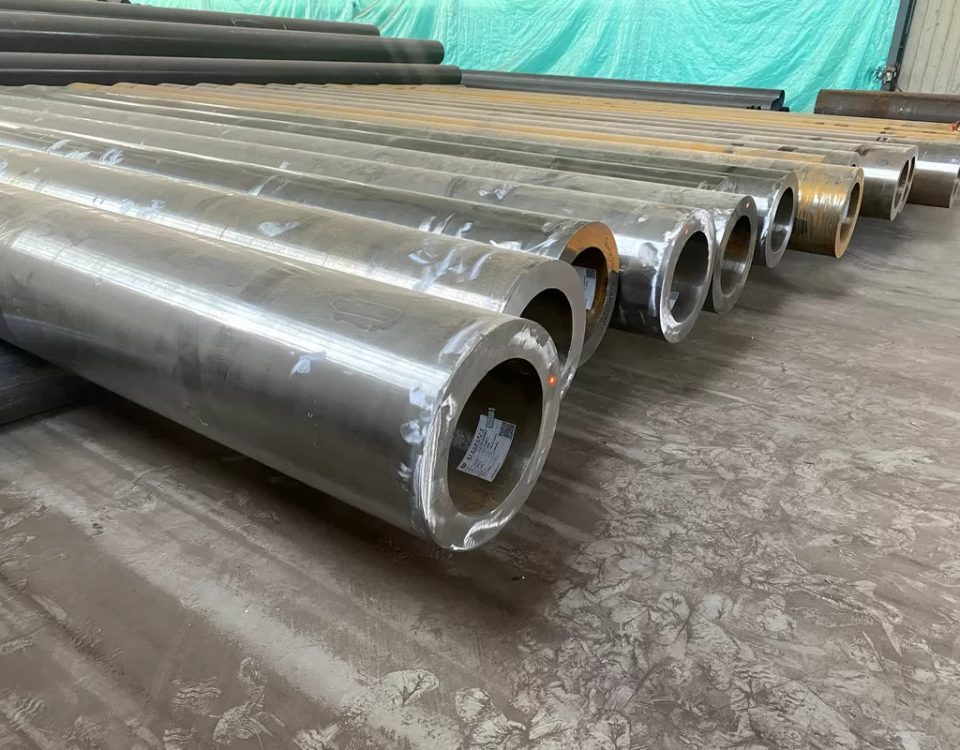
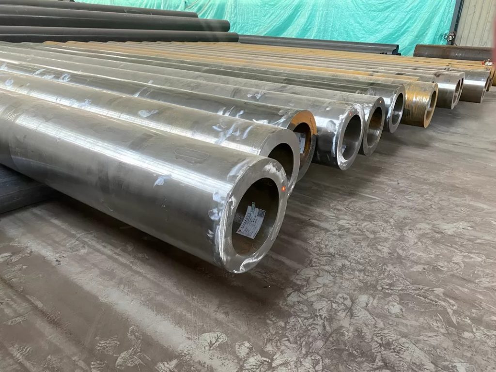
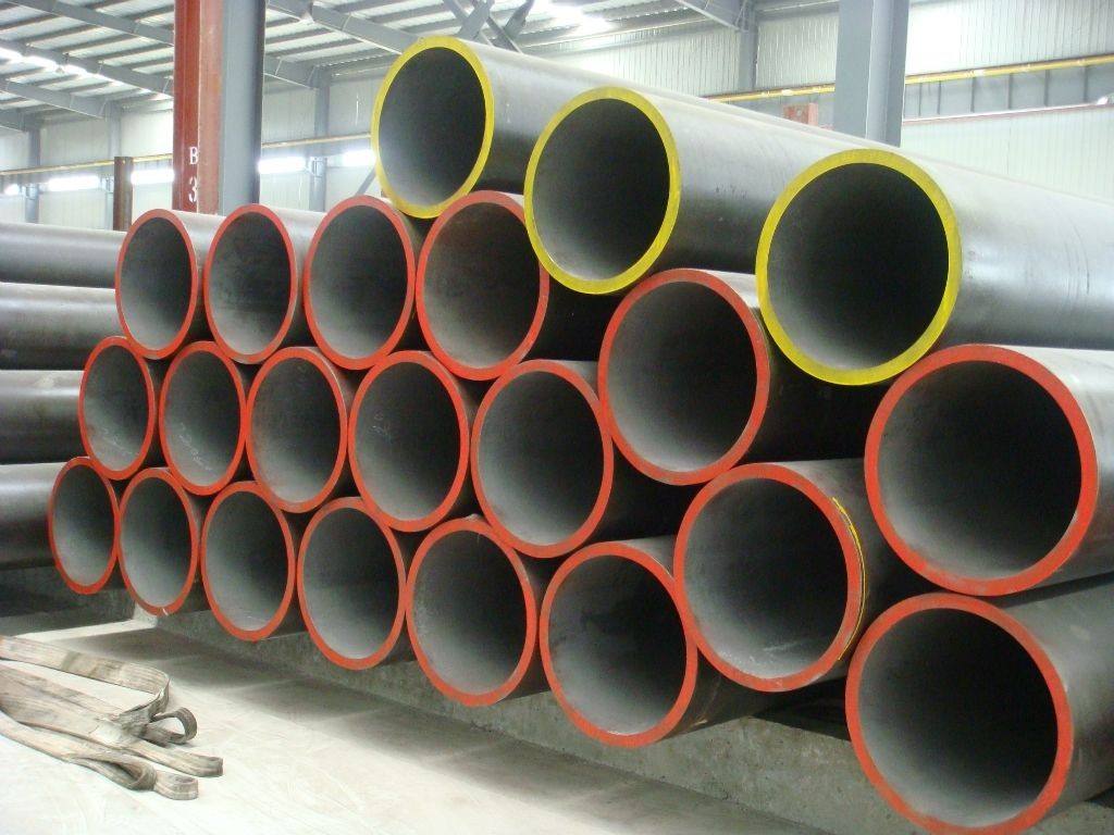
Casing is typically made from carbon steel, but as the primary structural component of the well the grade of steel used to make the casing, and the specifications of the finished material, are very important.
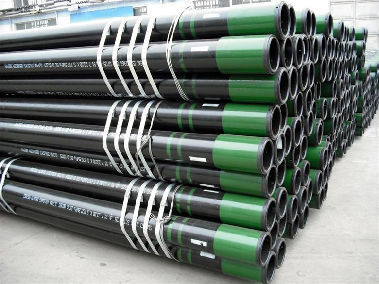
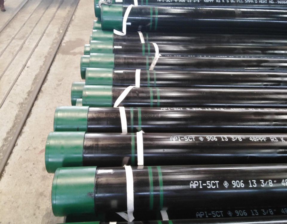
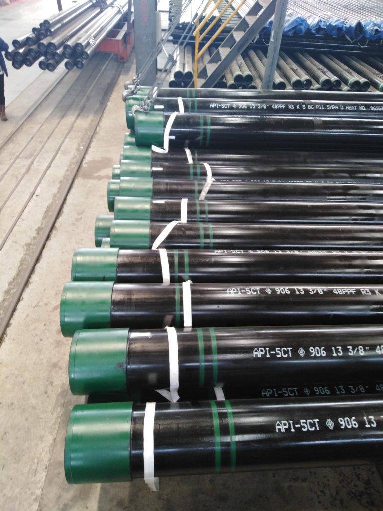
Specification for API 5CT seamless casing pipe
| Outsider Diameter | Wall Thickness | Grade | Thread | ||
| Inch | mm | kg/m | 1b/ft | J55/K55/N80/L80/P110 | STC/LTC/BTC |
| 4 1/2″ | 114.3 | 14.14-22.47 | 9.50-15.10 | J55/K55/N80/L80/P110 | STC/LTC/BTC |
| 5″ | 127 | 17.11-35.86 | 11.50-24.10 | J55/K55/N80/L80/P110 | STC/LTC/BTC |
| 5 1/2″ | 139.7 | 20.83-64.14 | 14.00-43.10 | J55/K55/N80/L80/P110 | STC/LTC/BTC |
| 6 5/8″ | 168.28 | 29.76-47.62 | 20.00-32.00 | J55/K55/N80/L80/P110 | STC/LTC/BTC |
| 7″ | 177.8 | 25.30-84.98 | 17.00-57.10 | J55/K55/N80/L80/P110 | STC/LTC/BTC |
| 7 5/8″ | 193.68 | 35.72-82.30 | 24.00-55.30 | J55/K55/N80/L80/P110 | STC/LTC/BTC |
| 8 5/8″ | 219.08 | 35.72-72.92 | 24.00-49.00 | J55/K55/N80/L80/P110 | STC/LTC/BTC |
| 9 5/8″ | 244.48 | 48.07-112.51 | 32.30-75.60 | J55/K55/N80/L80/P110 | STC/LTC/BTC |
| 10 3/4″ | 273.05 | 48.74-126.94 | 32.75-85.30 | J55/K55/N80/L80/P110 | STC/LTC/BTC |
| 11 3/4″ | 298.45 | 6250-105.66 | 42.0-71.00 | J55/K55/N80/L80/P110 | STC/LTC/BTC |
| 13 3/8″ | 339.73 | 71.43-107.15 | 48.00-72.00 | J55/K55/N80/L80/P110 | STC/LTC/BTC |
| 16″ | 406.40 | 96.73-162.21 | 65.00-109.00 | J55/K55/N80/L80/P110 | STC/LTC/BTC |
| 18 5/8″ | 473.08 | 130.22 | 87.50 | J55/K55/N80/L80/P110 | STC/LTC/BTC |
| 20″ | 508.00 | 139.89-197.93 | 94.00-133.00 | J55/K55/N80/L80/P110 | STC/LTC/BTC |
Most countries follow American Petroleum Institute (API) standards for the design, manufacturing, testing, and transportation of oil and gas casing used in wells that will be hydraulically fractured. According to API’s Hydraulic Fracturing Operations—Well Construction and Integrity Guidelines, casing must meet strict requirements for compression, tension, collapse, and burst resistance, quality, and consistency. Well casing should withstand hydraulic fracturing pressure, production pressures, and corrosive conditions. Used or reconditioned casing should meet the same API performance requirements as new casing.
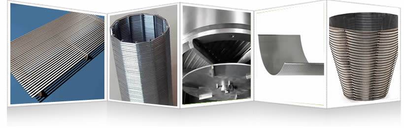
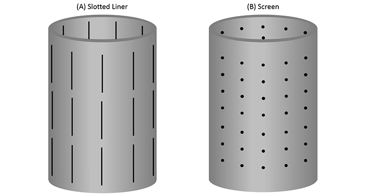
Well screen pipe definition:
A well screen is a filtering device that serves as the intake portion of wells constructed in unconsolidated or semi-consolidated aquifers.
The screen permits water to enter the well from the saturated aquifer, prevents sediment from entering the well, and serves structurally to support the aquifer material. The importance of a proper well screen cannot be overemphasized when considering the efficiency of a well and the log-term cost to its owner.
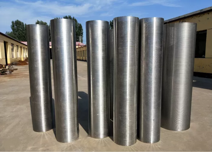
Well screens are manufactured from a variety of materials and range from crude handmade contrivances to highly efficient and long-life models made on machines. The value of a screen depends on how effectively it contributes to the success of a well.
Wedge wire is known as profile wire screen, V- wire screen, and wedge wire screen. And it is created by wrapping a profile wire cylindrical around longitudinal placed support rods. All wires and rods are resistance welded at each point of contact. The numerous combinations of profile wires and support rods, and the wide range of apertures between the wires and rods allows us to design a screen according your technical or cosmetic specification. It is custom made for the application.
Important screen criteria and functions include:
Criteria:
1. large percentage of open area
2. non clogging slots
3. resistant to corrosion
4. sufficient column and collapse strength
Functions:
1. easily developed
2. minimal incrusting tendency
3. low head loss through the screen
4. control sand pumping in all types of aquifers
Continuous-Slot Screen
The continuous-slot screen is widely used throughout the world for water, oil, and gas wells, and is the dominant screen type used in the water well industry. It is made by winding rolled wire, triangular in cross section, around a circular array of longitudinal rods.