
Aluminum Brass Tubes Inspection report
June 29, 2018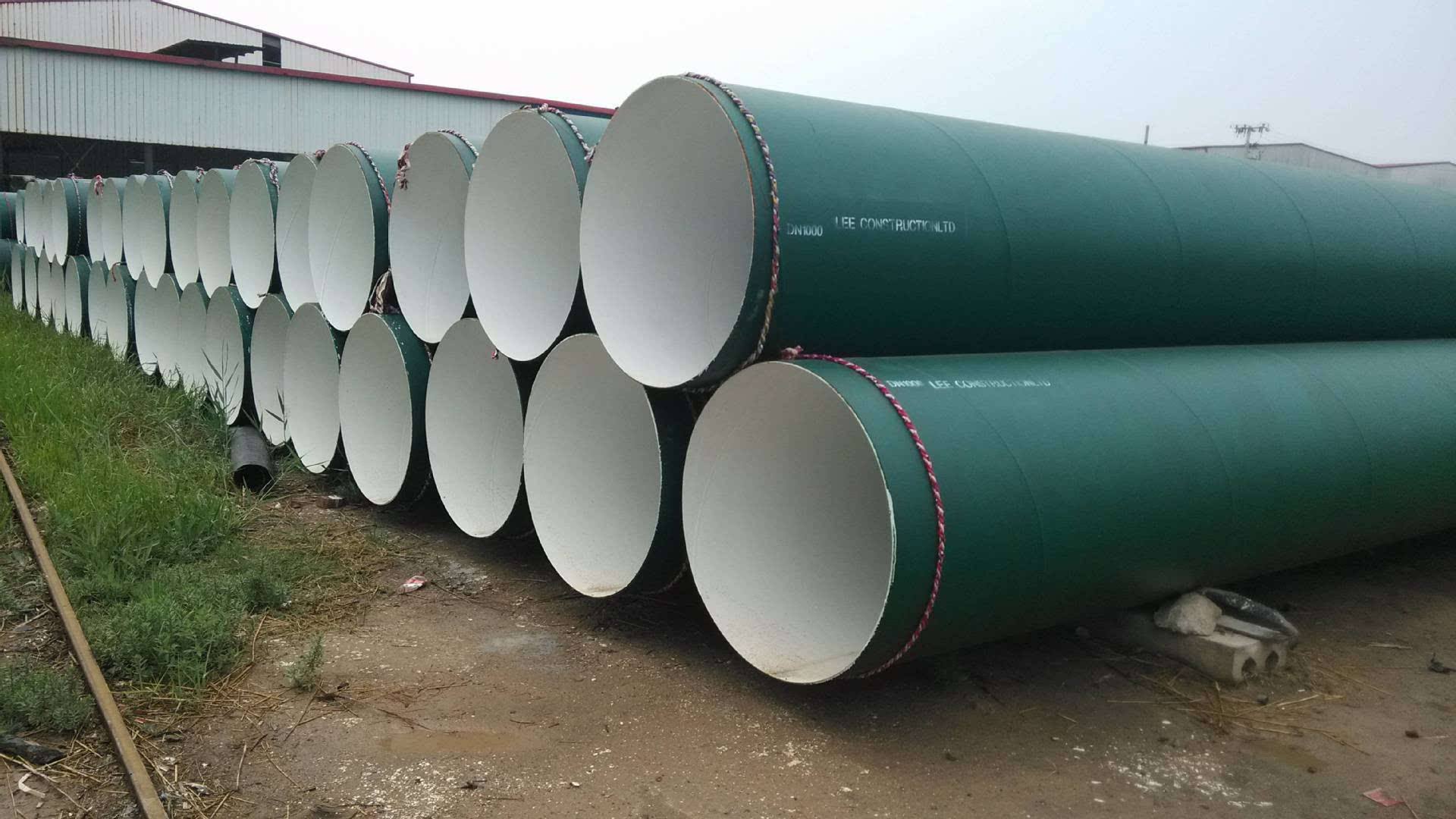
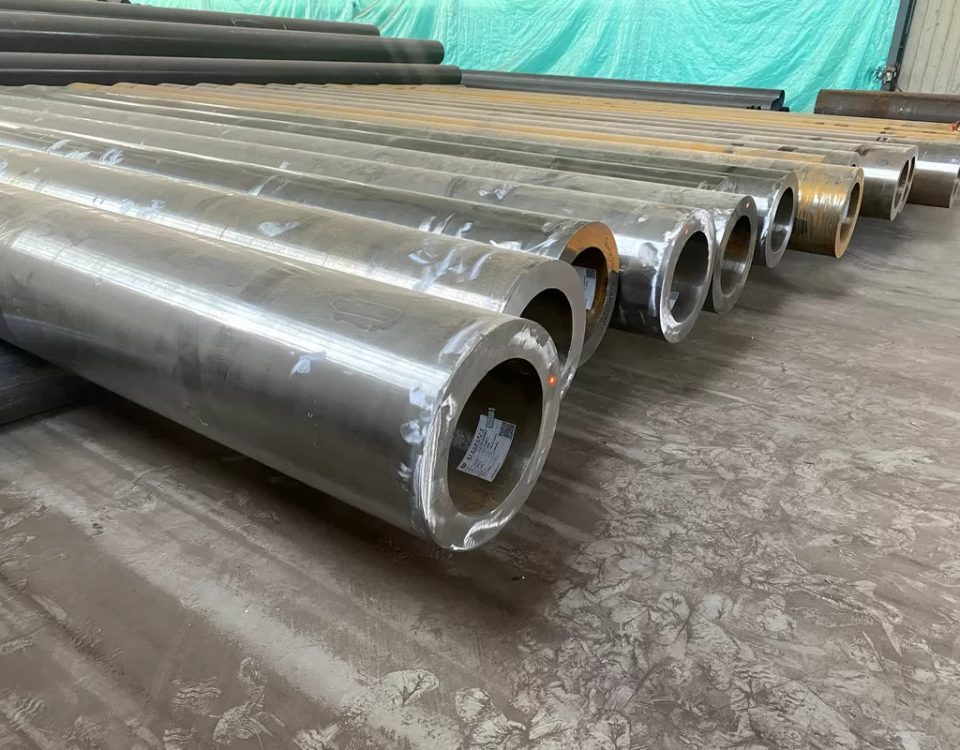
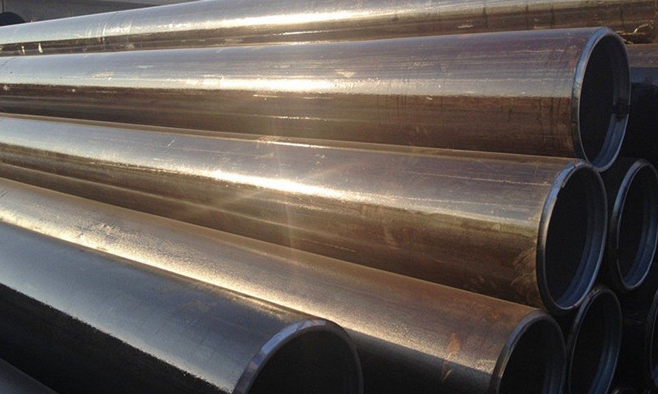
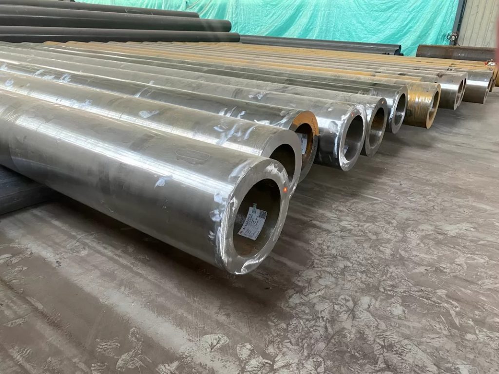
Steel Pipe Coating Solution
July 19, 2018
JOINING METHODS AND PIPE INSTALLATION
This data sheet describes the most common joining methods of steel water mains and the most important phases of installation.
Applications • water mains • sewage pipes
1. Trench, foundation and filling
The trench is dug wide enough, according to Figure 1, so as to have enough working space on both sides of the pipeline. If necessary, a levelling course is laid on the bottom of the trench. It is to be at least 150 mm thick measured from the exterior bottom of the pipe (See Fig. 2). The max. allowed grain size of the natural stone material used for levelling is always 60 mm, while the max. allowed grain size of the mineral aggregate in direct contact with the pipe coating is 32 mm. No sharp-edged stones are allowed in the levelling layer, and frozen levelling material must not be used. If the subsoil is soft, the pipeline may have to be founded on grid or even on piles.
The entire length of the underside of each pipe must rest on the bottom of the trench except for a distance of about half a metre from the sleeve in both directions (See Fig. 3). Each pipe of the installed line must carry, in addition to its own weight, also the weight of the water and the backfill, as well as other possible external loads.
If support planks or the like are used in installing an earth-covered pipeline, they must be removed before filling in the trench. The initial fill material must meet the same requirements as the levelling course and must be compactable sandy moraine or moraine gravel around the bottom half of the pipe – silt and clay may also be used around the upper half. Fill material must not be dropped onto a pipe so that it moves or gets damaged. It must be placed as evenly as possible on both sides of the pipe and tamped underneath and along the sides minding the pipe’s coating, and finally compacted.
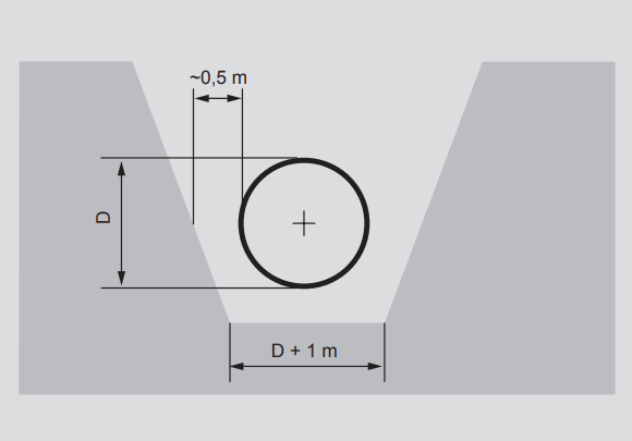
Figure-1.-Trench
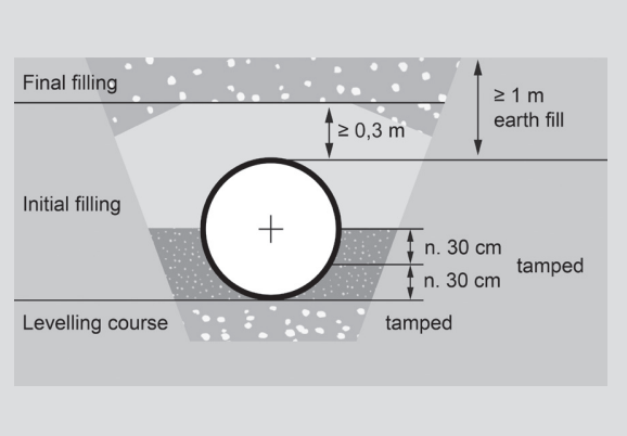
Figure-2.-Filling-of-trench
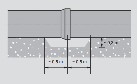
Figure-3.-Trench-bottom-at-sleeve
The main principle in filling a trench is that pipes, especially joints, must have sufficient lateral support against overhead loads. Therefore, the initial fill along the sides is tamped mechanically halfway up the pipe in layers of about 30 cm to at least 90% Proctor density, ensuring, however, that the compaction does not lift the pipe up.
The degree of compaction must be determined by measurements. The vibration panel must at no time touch a pipe or fitting to avoid damage to coating. Mechanical compaction above the pipe is allowed only after 50 cm of fill has been placed on top (See Fig. 2). After final filling, there must be a layer of fill material at least one metre thick, measured from the top of the pipe, containing no stones or boulders more than 300 mm in diameter. Any stone or boulder in the final fill material must not be located closer to the pipe than its diameter. Excavated soils may be used outside traffic areas. A pipeline .
must always be plugged temporarily as installation is interrupted in order to prevent impurities from entering pipes. During installation, the water level in the trench must be kept low enough so that buoyancy will not move nor water damage the installed pipe. More detailed instructions on the installation of plastic coated pipings are provided in the municipal engineering regulations of each country. When installing pipes in areas where there are roads or railway lines, the instructions of the pertaining official are to be followed.
2. Joining methods
General
Pipe joints (Fig. 4) are used to join pipes and fittings into an integrated pipeline. Joints can be divided into two main types: tension-resistant and non-resistant ones. Joints may also be divided by applications as follows:
2.1 Butt joint
Used primarily in tension-resistant pressure lines such as oil, natural gas and district heating pipelines. Used in water pipelines especially with pipe sizes ≥ DN 600 when the joint can be repaired from the inside after welding. For a more detailed description, see Figure 6 on Page 5. A Welding collar is used to join new piping or a fitting to an existing line. Internal welding and completion of concrete lining require a manhole in connection with the joint. Installation of the welding collar is described in Figure 9.
2.2 DIN/G welded joint
Used in pipelines where easy installation of the tensionresistant joint and the possibility of making less than 1.0 degree bends are a must. Welded from the outside. Suits pipe diameters DN 400–900 pressure class PN16 and DN1000-1200 pressure class PN10. Only internal concrete lining is used with this type of sleeve, no painting is done. The DIN/G joint is manufactured at the works by incorporating a rubber ring in the concrete lining, which means there is no need to complete the internal concrete lining on site. The rubber ring prevents water from changing in the gap of the sleeve joint.

2.3 OV welded joint
Used in water lines to facilitate installation and to allow 1.5 – 3.0 degree bends at joints. Since the joint is welded from the inside to make it tension resistant, it is suitable for diameters ≥ DN 600 and pressures up to 20 bar. For a more detailed description, see Section 3.3 and Figure 8.
2.4 Flanged joint
Flanged joints are widely used in industry. With underground pipes, flanged joints are used e.g. in connection with valves and manholes. For a more detailed description, see Section 3.4 and Figure 10. The joints can be sealed e.g by Klinger-KGS gaskets.
2.5 Coupling joint
Steel pipes may also be joined by various mechanical pipe couplings such as those manufactured by Straub, VikingJohnson and Victaulic. Then, the ends of pipes are lathed and external weld seams are ground to fit the couplings. For a more detailed description, see Section 3.5.
2.6 Welding collar
A welding collar is used when connecting new piping or a single new component to an existing piping. The installation of a welding collar is described in Figure 9. When a single new component is installed, it must also have a manhole so that the internal lining can be repaired. The welding collar can be welded only externally up to pressure class PN10, but it also requires internal welding in pressure class PN16. After welding, the internal lining and external corrosion protection coating are completed.
2.7 Selection of joining method
Welding is normally used with underground installation. Welded sleeve joints facilitate installation and allow small bends without angular pipe fittings. In subsoils of low bearing capacity (clay and silt), a welded joint is more secure than a coupling joint. In case a coupling joint is used in weak soils, it is recommended to use sturdier couplings.The coupling must be supported on a concrete slab or the like to eliminate shear stresses. At high water pressures (≥ 10 bar) it is also advisable to use a sturdier type of coupling. The teeth of tension-resistant, toothed couplings damage external protective coatings. Therefore, their use should be limited mainly to dry, indoor installations where external corrosion protection is not needed.
Tensionresistant flanged joints are used in institutional and industrial installations to facilitate disassembly. Tensionresistant joints must always be used in submerged installation. When using DIN/G type sleeves, pipes are only lined with concrete internally, no painting is done.
3. Installation
Plastic end covers
The plastic covers at the ends of the pipes shall not be removed until shortly before installation in order to avoid excessive curing or soiling of the internal concrete lining during storage. In summer, the external black PUR coating on the pipe parts is covered with white plastic for the entire storage period, as heat from the sun will soften the coating.When removing the plastic covers, a visual inspection of the ends, internal surfaces and sleeves of the pipes is performed. Hairline cracks in the concrete lining which are caused by excessive curing can be removed in summer by wetting the concrete with household water now and again.
3.1. Butt joint
General
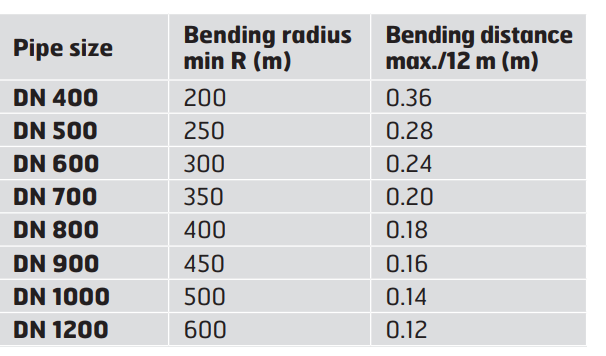
Tension-resistant butt joints (Fig. 6) are used with the entire range of pipe sizes. The joints are welded from the outside with basic electrodes. Working temperature need not be raised. The joints as such do not allow bends, but the end of a pipe can be cut at an angle, or a pipeline with internal concrete lining can be bent safely, if necessary, to the minimum radius of curvature given in the table.
Welding
The welder must have at least the competence required by Standard EN 9606-1. The weld quality class is set out in Standard EN ISO 5817, Class C.Pipes are adjusted for welding. The weld cavity-reducing effect of tacking and welding must be considered in determining the width of the weld cavity (2 – 4 mm). After tacking, the joints are welded in 2 – 3 runs with a dry basic electrode, such as Esab OK 48.00, Elga P48, Böhler Fox EV 48, Filarc 35 or equivalent. The thickness of the electrode is determined by the pipe wall thickness, the mode of welding, the type of run and welding position, as well as the competence of the welder. The welding values are selected as per instructions of the welding consumable suppliers. Running of a welding procedure test in accordance with EN ISO 15614-1 is recommended prior to commencing welding.
Control of welded joint
All welds are to be inspected at least visually. Beginning and end defects, undercuts, cracks, etc. surface defects are ground or repaired by welding. Additionally recommendation is that at least 10% of welds are examined by magnetic particle testing. Basic requirement is also that at least 5 welds of every welder are to be examined and if any welds fails, test frequency will be higher. Moreover, the tightness of the joints is tested by water pressure test after the pipeline is completed.
Completion of internal concrete lining
Internal concrete lining is completed with pipe sizes ≥ DN 600. After welding, loose rust and weld slag and Figure 6. Butt joint All dimensions in millimetres. min. 50 Shrinkable sleeve or corrosion protection tape DIN 30670 N-n 6 any possible concrete coming off the joints is brushed off the interior surface. In winter conditions the joint area is heated with a gas flame. The joint area is first moistened and then coated with mortar that consists of equal parts of sand and cement (SR cement). The sand is to be sufficiently clean with a grain size of 0.125 – 1.5 mm. Enough water is added to make a fairly stiff mortar. Only the amount of mortar and cement used in one hour is to be mixed. The mortar is spread with a trowel to the level of the original lining. After about 2 hours the area is rubbed with a wet sponge. Under site conditions, concrete requires at least 5 days to cure. If possible, the joint area should be kept damp and at over +5 ºC during that period. In winter conditions a warm air blower can be used for heating. Frost proof cement must not be used as it contains water-soluble admixtures unsuitable for drinking water applications.
Completion of internal painting
Internal painting is completed with pipe sizes ≥ DN 600. The joint area is treated as per instructions of the paint manufacturer. Completion of external coating Bare steel surfaces are cleaned with a steel brush (degree of cleanness St 2), dried with liquid gas flame and anticorrosive painted (example Temaprime EE) before sleeve will be added. The PE coating is roughened over a distance of about 100 mm. The cleaned and warmed joint area is protected by a heat-shrinkable sleeve or corrosion protection tape (Canusa, Raychem, Denso, Stopaq etc.) as per manufacturer’s instructions.