
Corten Steel ASTM A242 Pipe
December 27, 2025
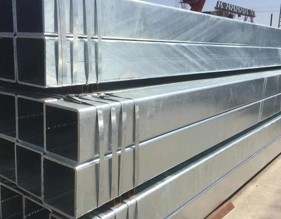
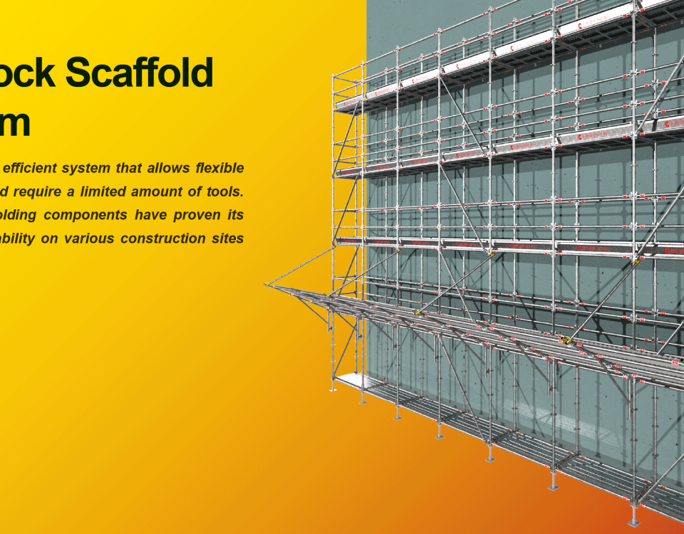
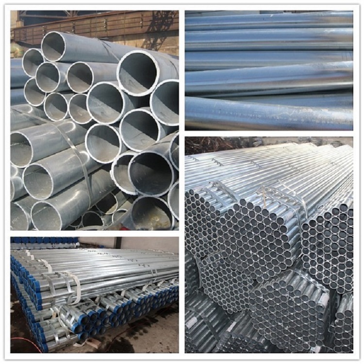
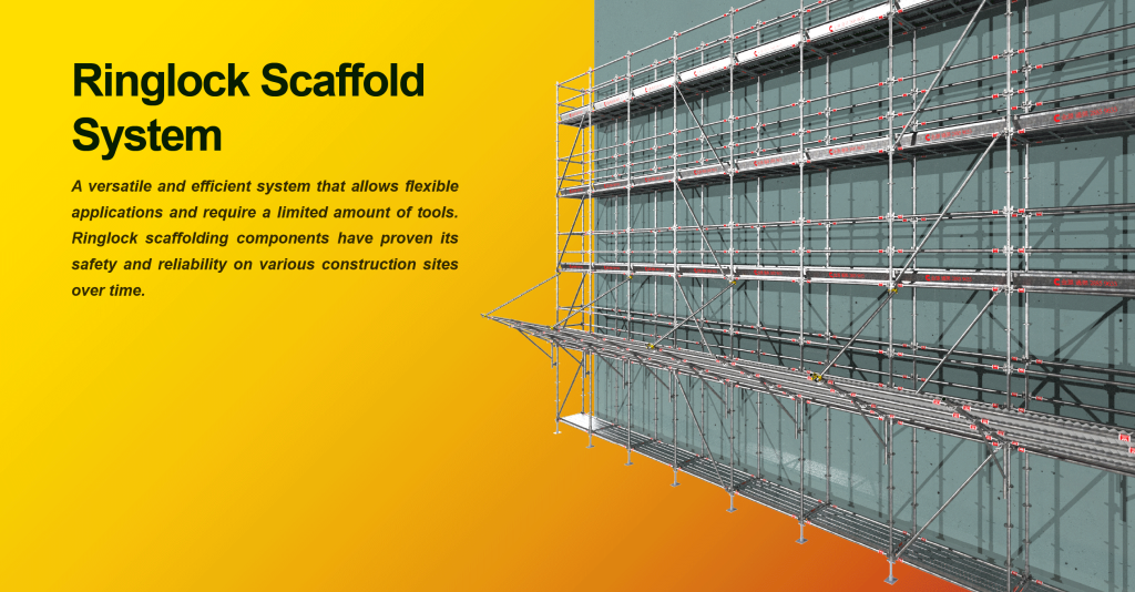
Galvanized Steel Scaffolding Pipes – Schedule 40 vs. Schedule 80
January 2, 2026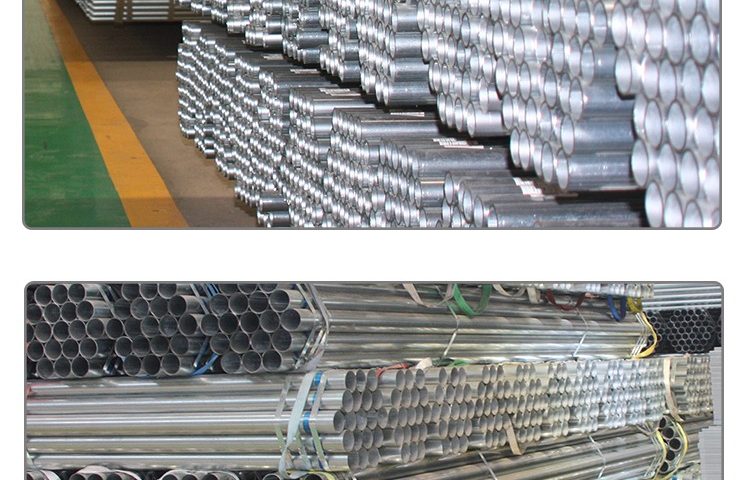
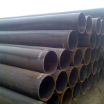
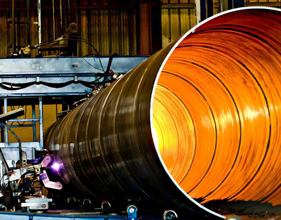
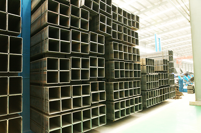
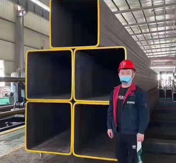
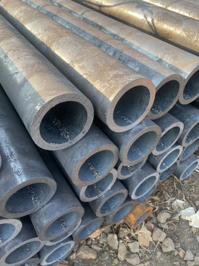
When I begin to contemplate the structural essence of a Galvanized Steel Schedule 40 pipe, specifically within the demanding context of scaffolding, my mind immediately moves past the surface-level geometry and into the microscopic architecture of the iron-carbon lattice. We aren’t just talking about a hollow cylinder; we are discussing a calibrated equilibrium between ductility and ultimate tensile strength, a balance necessitated by the life-critical nature of vertical access. I find myself thinking about the “Schedule 40” designation—it’s more than a wall thickness; it represents a specific resistance to buckling and a moment of inertia that must remain consistent across miles of construction sites. The steel starts as a molten dialogue between iron ore and precisely metered carbon, where the cooling rate dictates the formation of pearlite and ferrite. If the carbon equivalent is too high, we face weldability issues at the joints; if it’s too low, the pipe lacks the structural “backbone” to resist the immense compressive loads of a multi-story scaffold. Then there is the galvanization—this isn’t just a coating, it’s a metallurgical bond. I’m thinking about the Sandelin Effect, where silicon and phosphorus levels in the steel can cause the zinc-iron alloy layers to grow uncontrollably, potentially leading to a brittle, dull gray finish rather than the resilient, spangled armor required for outdoor longevity. The chemistry of the molten zinc bath, usually kept around 450°C, initiates a diffusion process where the zinc atoms literally migrate into the steel surface, creating a series of intermetallic phases—the Gamma, Delta, and Zeta layers—each with its own hardness profile, topped by the pure zinc Eta layer. This sacrificial protection is the only thing standing between the structural integrity of the pipe and the relentless oxidation of a humid construction environment. As I look deeper into the tensile requirements, I realize that the elongation percentage is just as vital as the yield point; a scaffold pipe must be able to deform slightly under extreme shock loads without catastrophic fracturing. It is this “forgiveness” in the material—this ability to absorb energy through plastic deformation before reaching the ultimate tensile limit—that makes Schedule 40 steel the industry standard. I’m considering the heat treatment too; normalizing the steel to refine the grain size is what gives the pipe its uniform response to stress. Without a controlled grain structure, you get localized weak points where cracks can propagate. Everything is interconnected: the chemistry dictates the grain, the grain dictates the strength, and the strength dictates the safety of the worker standing twenty stories above the ground.
Technical Analysis of Galvanized Steel Schedule 40 Pipe for Scaffolding
The Metallurgical Foundation: Chemical Synergy and Structural Integrity
The production of high-grade scaffolding pipe begins long before the rolling mill, starting instead with the rigorous control of the chemical melt. In the context of Schedule 40 pipe, which is frequently governed by standards such as ASTM A53, BS 1387, or EN 10219, the chemical composition is the primary determinant of both the mechanical performance and the success of the subsequent galvanization process. Carbon serves as the primary hardening agent; however, in scaffolding applications, the carbon content is typically capped to ensure that the pipe remains weldable and ductile. A high carbon content might increase the yield strength, but it simultaneously increases the risk of brittle failure—a catastrophic scenario in scaffolding where the structure must withstand dynamic loads and vibrations. Manganese is added to improve the strength-to-weight ratio and to act as a deoxidizer, but more importantly, it combines with residual sulfur to form manganese sulfides, preventing “hot shortness” during the hot-rolling process.
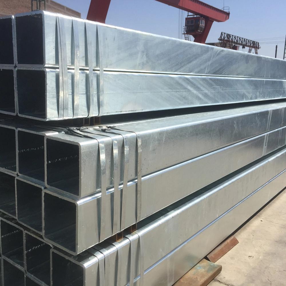
The presence of silicon and phosphorus must be monitored with extreme precision due to their influence on the hot-dip galvanizing (HDG) reaction. If silicon levels fall within the “Sandelin Range” (0.03% to 0.12% or above 0.25%), the reaction between the iron and the molten zinc becomes hyper-active, leading to an excessively thick, brittle coating that may flake off during the rough handling typical of construction sites. Therefore, the “aluminum-killed” or “silicon-killed” nature of the steel must be specified to ensure a smooth, adherent, and aesthetically consistent zinc layer.
Table 1: Typical Chemical Composition (Reference: ASTM A53 Grade B)
| Element | Composition (%) | Role in Scaffolding Performance |
| Carbon (C) | 0.30% Max | Balances hardness with ductility; ensures ease of welding. |
| Manganese (Mn) | 1.20% Max | Increases tensile strength and improves grain structure. |
| Phosphorus (P) | 0.05% Max | Limited to prevent cold-shortness (brittleness at low temps). |
| Sulfur (S) | 0.045% Max | Kept low to maintain internal structural purity. |
| Copper (Cu) | 0.40% Min* | (Optional) Enhances atmospheric corrosion resistance. |
| Nickel (Ni) | 0.40% Max | Improves toughness and impact resistance. |
Thermal Processing and Grain Refinement
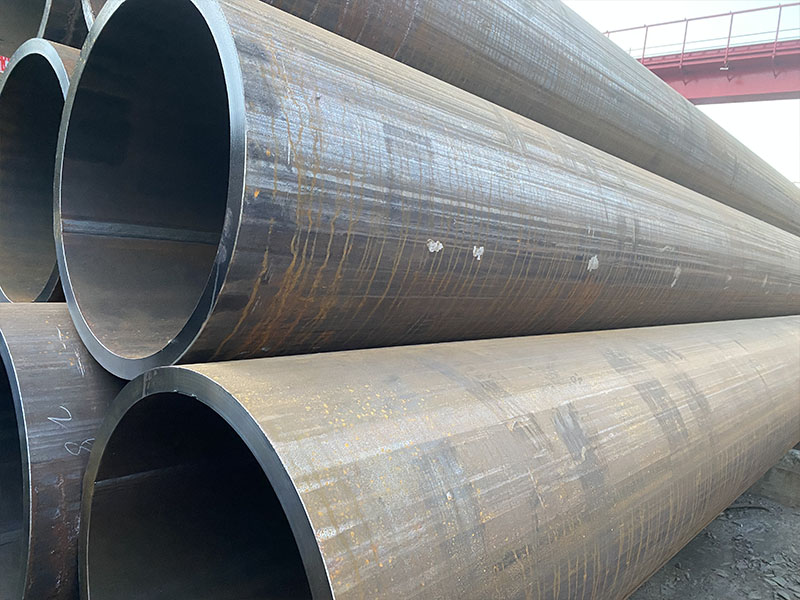
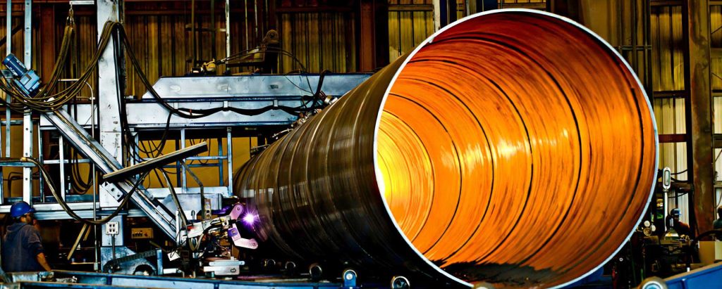
Heat treatment is the “silent” phase of production that defines the internal uniformity of the Schedule 40 pipe. For scaffolding, the pipe is often produced as Electric Resistance Welded (ERW), where the longitudinal seam is fused using high-frequency current. Without subsequent heat treatment, the Heat Affected Zone (HAZ) around the weld would possess a different microstructure—often more martensitic and brittle—than the parent metal. To rectify this, the pipe undergoes Normalizing or Seam Annealing.
Normalizing involves heating the steel to a temperature above its upper critical point (the $Ac_3$ line in the iron-carbon phase diagram, typically around 850°C to 950°C) and then cooling it in still air. This process transforms the coarse, distorted grains resulting from the rolling or welding process into fine, uniform, equiaxed grains of ferrite and pearlite. A finer grain size, according to the Hall-Petch relationship, simultaneously increases both the yield strength and the toughness of the material. In scaffolding, this uniformity is crucial because the pipe is subjected to complex stress states, including axial compression, bending moments at the couplers, and local crushing forces from scaffolding clamps.
Table 2: Heat Treatment Requirements for High-Durability Scaffolding Pipe
| Process | Temperature Range | Objective |
| Normalizing | 880°C – 940°C | Homogenizes the microstructure and refines grain size for toughness. |
| Stress Relieving | 540°C – 650°C | Reduces internal residual stresses post-welding or cold-forming. |
| Full Annealing | 800°C – 870°C | Maximizes ductility and softens the metal for extreme forming. |
Mechanical Dynamics and Load-Bearing Capacity
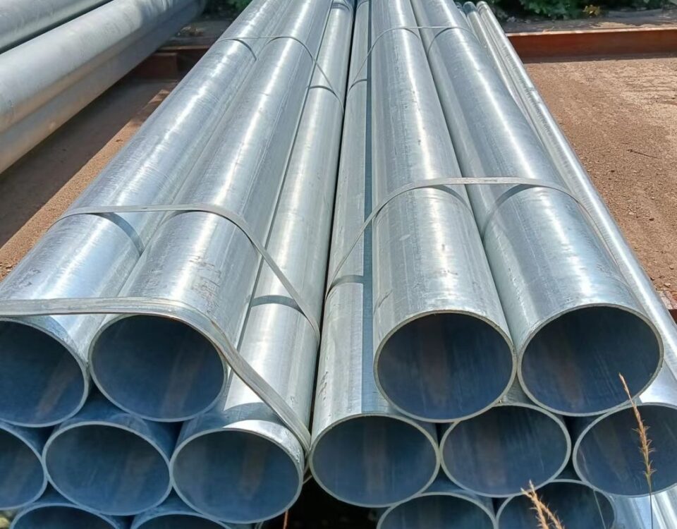
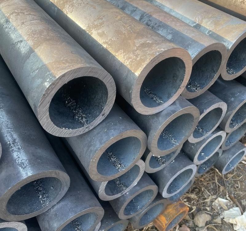
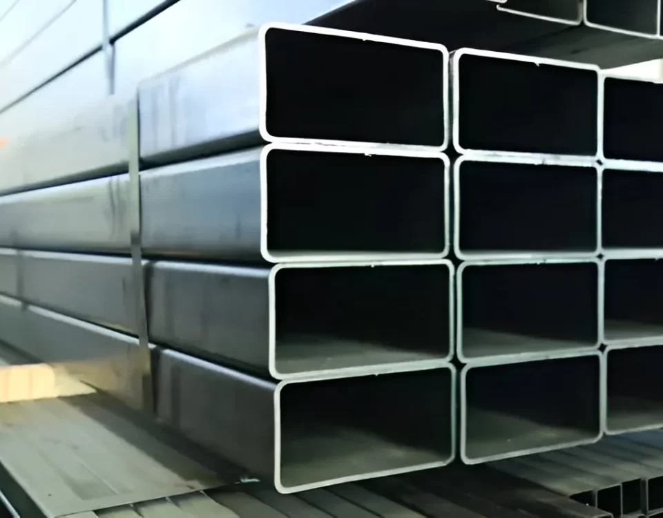
The “Schedule 40” designation refers to the pipe’s wall thickness relative to its diameter. For a standard 1.5-inch nominal pipe size (commonly used in scaffolding), Schedule 40 provides a wall thickness of approximately 3.68mm (0.145 inches). This thickness is the sweet spot for scaffolding: it is heavy enough to resist local deformation (denting) from clamps and falling objects, yet light enough to be manually handled by workers.
The Tensile Requirements are the benchmarks by which the safety factor of the scaffold is calculated. The Yield Strength is perhaps the most critical value; it represents the point at which the steel will no longer return to its original shape once the load is removed. Scaffolding design codes (like OSHA in the US or EN 12811 in Europe) rely on these values to determine the maximum allowable height and load-carrying capacity of the structure. The Ultimate Tensile Strength (UTS) provides the “buffer” or safety margin. If a scaffold is overloaded, the gap between the yield point and the UTS allows the pipes to visibly bend and deform—providing a clear warning to workers—rather than snapping suddenly.
Table 3: Tensile and Mechanical Requirements (Reference: ASTM A53 / Grade B)
| Property | Value (Metric) | Value (Imperial) | Importance for Scaffolding |
| Tensile Strength, min. | 415 MPa | 60,000 psi | Overall structural integrity against breaking. |
| Yield Strength, min. | 240 MPa | 35,000 psi | Resistance to permanent deformation under load. |
| Elongation in 2 inches | ~20% – 35%* | ~20% – 35%* | Ability to withstand impact and seismic shifts. |
| Hydrostatic Test | Variable | Variable | Ensures no micro-fissures in the pipe wall. |
| *Note: Elongation varies based on specimen thickness and grade. |
The Galvanization Barrier: Physics of Corrosion Resistance
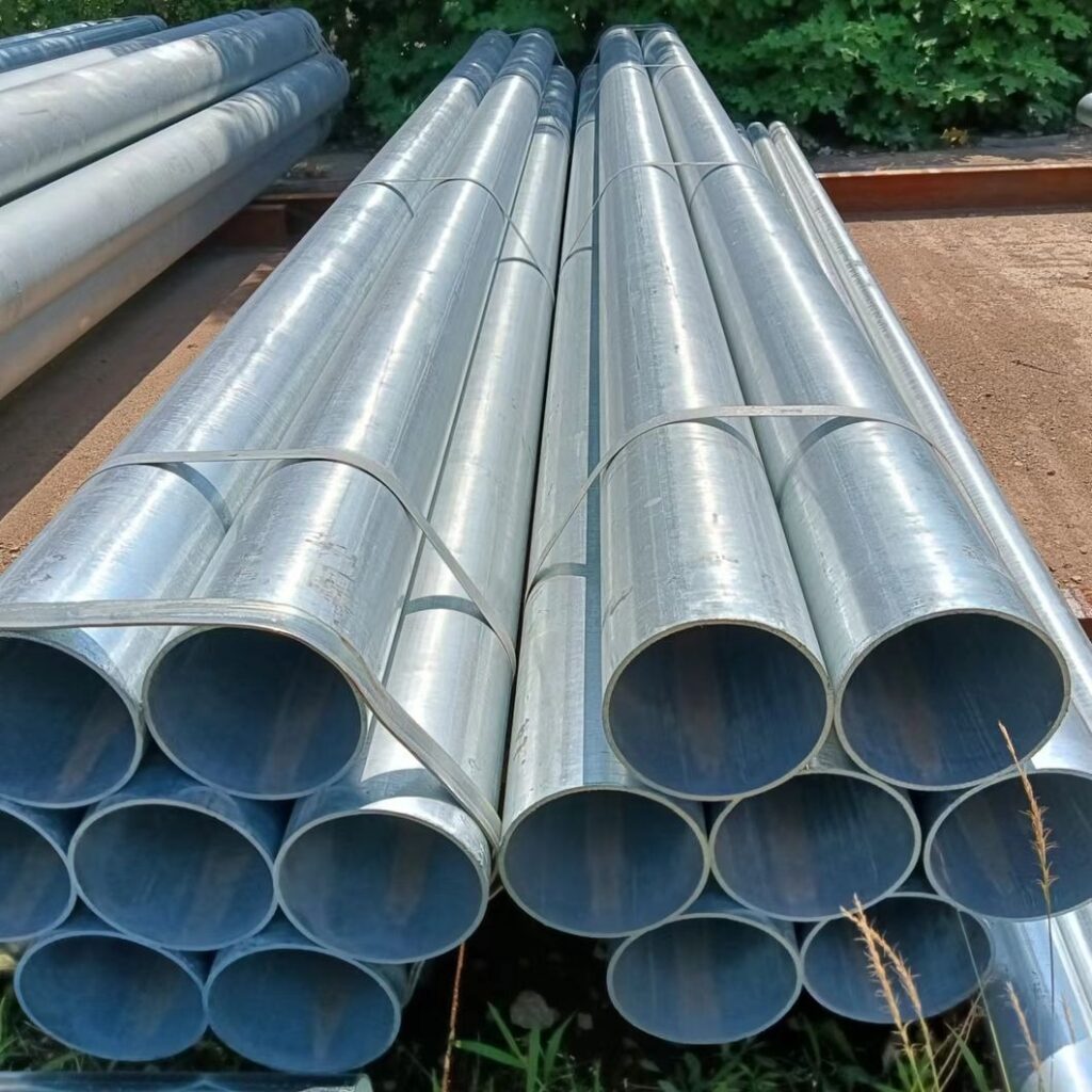
The final, and perhaps most visible, technical feature of your product is the hot-dip galvanization. Unlike paint, which acts as a simple barrier, galvanization provides cathodic protection. If the surface is scratched, the surrounding zinc will oxidize preferentially to the steel, effectively “healing” the breach. The process creates a complex multi-layered structure:
- Eta Layer (100% Zn): The soft, ductile outer layer that provides the initial impact resistance.
- Zeta Layer (94% Zn, 6% Fe): A layer of monoclinic crystals that are harder than the base steel.
- Delta Layer (90% Zn, 10% Fe): Provides a dense, compact bond.
- Gamma Layer (75% Zn, 25% Fe): The thin, extremely hard alloy layer that anchors the entire coating to the steel.
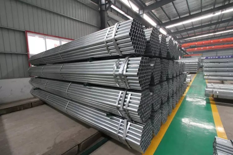
The thickness of this coating is usually measured in microns ($\mu m$) or ounces per square foot. For scaffolding used in coastal or industrial environments, a coating thickness of at least 65-85 $\mu m$ is standard, ensuring a service life of several decades without structural degradation.
The Galvanized Steel Schedule 40 Pipe is an engineered solution to a high-stakes environment. By integrating specific carbon-manganese chemistry, precise thermal normalizing, and a multi-layered zinc-iron alloy barrier, the product transitions from a mere industrial commodity to a critical safety component. The interplay between the wall thickness of the Schedule 40 standard and the mechanical properties of the Grade B steel ensures that the scaffold can withstand not only the static loads of masonry and personnel but also the dynamic, unpredictable stresses of wind and vibration.