
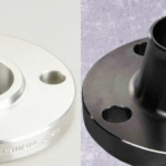
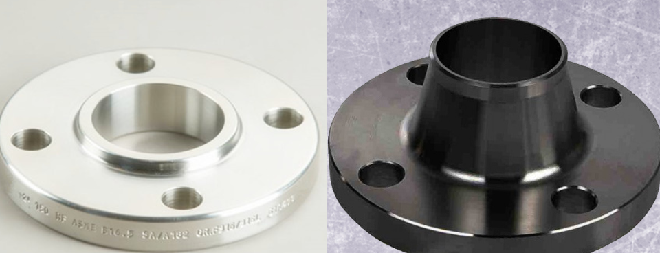
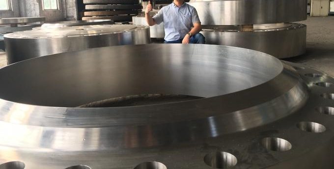
Weld Neck Pipe Flange (WNRF)
April 9, 2026
UL 852 Fire Sprinkler Pipe
May 17, 2026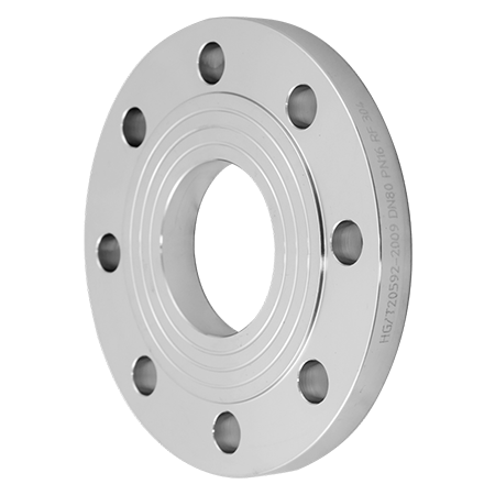
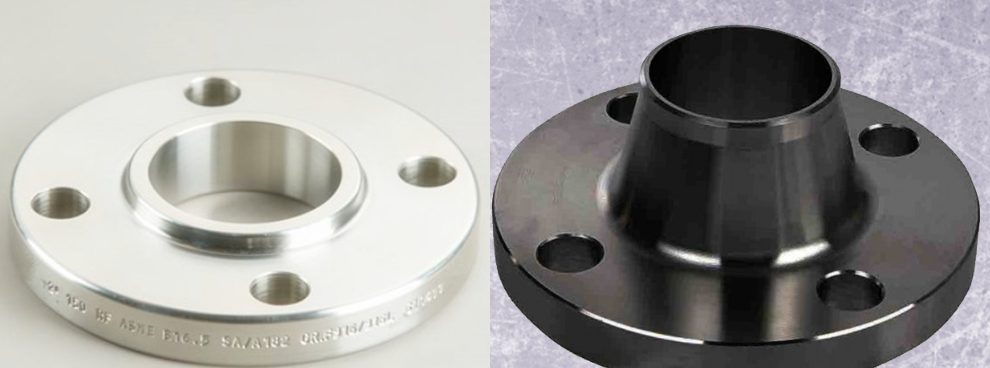
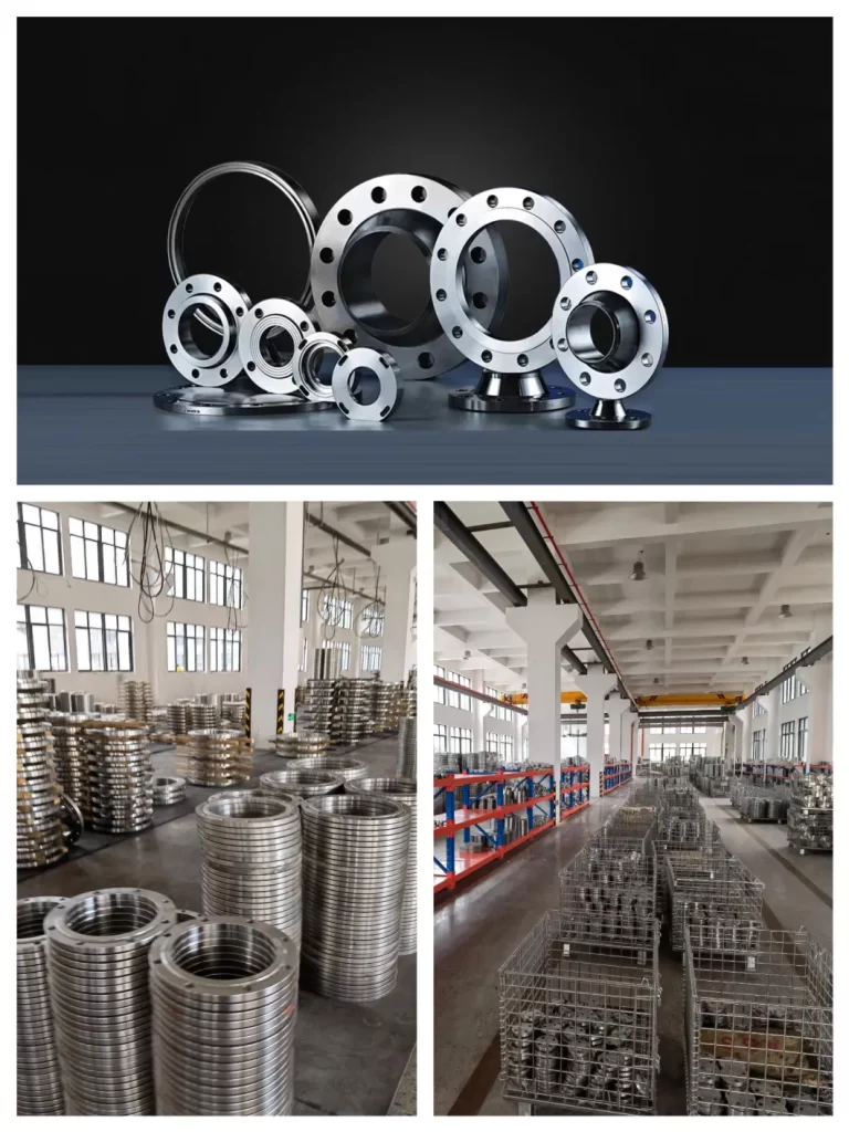
Slip-On Flanges (SO): Engineering Specification Guide
The definitive resource for Slip-On Pipe Flanges: Dimensional Matrices, Material Compliance (ASTM/DIN), and Pressure-Temperature Ratings for Industrial Piping Systems.
1. Functional Overview of Slip-On Flanges
The Slip-On Flange (SO Flange) is an essential piping component designed primarily for lower pressure and moderate temperature applications. It features a central bore slightly larger than the outside diameter (OD) of the pipe, allowing the pipe to slip through the flange before being secured via fillet welds on both the internal and external sides.
Due to the absence of a weld bevel, Slip-On flanges offer significant field flexibility, allowing engineers to adjust the pipe length precisely relative to the flange face before final welding.
Core Advantages & Applications:
- Ease of Alignment: Simpler to install than Weld Neck flanges.
- Cost-Effective: Lower manufacturing costs due to reduced material volume.
- Large Bore Utility: Ideal for large-diameter storage tank nozzles.
- Space Optimization: Available in hubless “Ring Style” for tight installations.
2. Manufacturing Standards & Material Compliance
We supply Slip-On flanges compliant with rigorous international standards to ensure interchangeability across global infrastructure projects.
Table 1: Governing Standards Matrix
| ASME / ANSI | DIN / European | Chinese (GB/HG) | JIS / Japanese |
|---|---|---|---|
| B16.5, B16.47 | DIN 2576, EN 1092-1 | GB/T9119, HG/T20592 | B2220 |
Table 2: Material Grade Selection (Stainless & Duplex)
| Category | Grade Specification |
|---|---|
| Stainless Steel 304 | F304, S30408, S30408II, S30400, 06Cr19Ni10 |
| Stainless Steel 316L | F316L, 31603, S31603, 022Cr17Ni12Mo2 |
| Duplex Steel | 2205 (F51), 2507 (F53), S22053 |
| High Temp Alloys | TP310S (06Cr25Ni20), TP321 (06Cr18Ni11) |
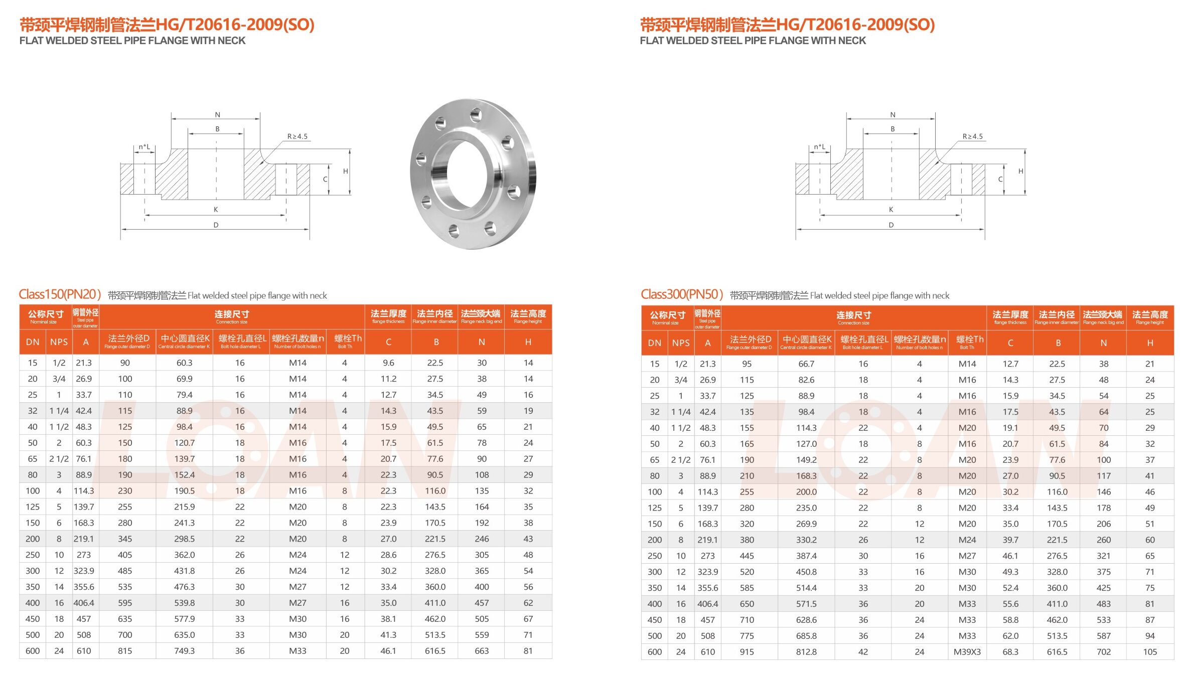
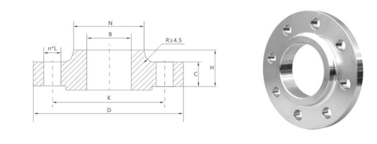
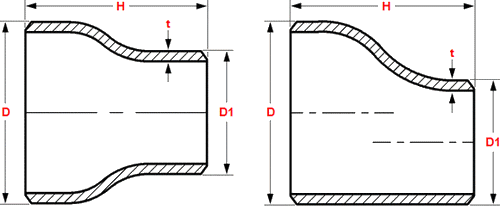
3. Slip-On Flange Dimensional Data (Class 150 – 600)
The following tables provide critical dimensions for Slip-On flanges according to ASME B16.5 / HG/T20616 standards. All measurements are in millimeters (mm) unless otherwise noted.
Matrix A: ASME Class 150 (PN20) Slip-On Flange
| NPS (Inch) | Pipe OD (A) | Flange OD (D) | PCD (K) | Bolt Holes (n) | Thick (C) | Inner Dia (B) | Hub Dia (N) | Height (H) |
|---|---|---|---|---|---|---|---|---|
| 1/2″ | 21.3 | 90 | 60.3 | 4 | 9.6 | 22.5 | 30 | 14 |
| 3/4″ | 26.9 | 100 | 69.9 | 4 | 11.2 | 27.5 | 38 | 14 |
| 1″ | 33.7 | 110 | 79.4 | 4 | 12.7 | 34.5 | 49 | 16 |
| 2″ | 60.3 | 150 | 120.7 | 4 | 17.5 | 61.5 | 78 | 24 |
| 4″ | 114.3 | 230 | 190.5 | 8 | 22.3 | 116.0 | 135 | 32 |
| 8″ | 219.1 | 345 | 298.5 | 8 | 27.0 | 221.5 | 246 | 43 |
| 12″ | 323.9 | 485 | 431.8 | 12 | 30.2 | 328.0 | 365 | 54 |
Matrix B: ASME Class 300 (PN50) Slip-On Flange
| NPS (Inch) | Pipe OD (A) | Flange OD (D) | PCD (K) | Bolt Holes (n) | Thick (C) | Inner Dia (B) | Hub Dia (N) | Height (H) |
|---|---|---|---|---|---|---|---|---|
| 1/2″ | 21.3 | 95 | 66.7 | 4 | 12.7 | 22.5 | 38 | 21 |
| 1″ | 33.7 | 125 | 88.9 | 4 | 15.9 | 34.5 | 54 | 25 |
| 3″ | 88.9 | 210 | 168.3 | 8 | 27.0 | 90.5 | 117 | 41 |
| 6″ | 168.3 | 320 | 269.9 | 12 | 35.0 | 170.5 | 206 | 51 |
| 10″ | 273.0 | 445 | 387.4 | 16 | 46.1 | 276.5 | 321 | 65 |
Matrix C: ASME Class 600 (PN110) Slip-On Flange
| NPS (Inch) | Pipe OD (A) | Flange OD (D) | PCD (K) | Bolt Holes (n) | Thick (C) | Inner Dia (B) | Hub Dia (N) | Height (H) |
|---|---|---|---|---|---|---|---|---|
| 1/2″ | 21.3 | 95 | 66.7 | 4 | 14.3 | 22.5 | 38 | 22 |
| 2″ | 60.3 | 165 | 127.0 | 8 | 25.4 | 61.5 | 84 | 37 |
| 4″ | 114.3 | 275 | 215.9 | 8 | 38.1 | 116.0 | 152 | 54 |
| 8″ | 219.1 | 420 | 349.2 | 12 | 55.6 | 221.5 | 273 | 76 |
| 12″ | 323.9 | 560 | 489.0 | 20 | 66.7 | 328.0 | 400 | 92 |
more data tables
4. Proper Installation and Welding Procedures
The reliability of a Slip-On flange joint depends entirely on the quality of the fillet welds. Standard practice requires two welds:
External Fillet Weld
Applied at the junction where the pipe exits the flange hub. This weld provides the primary structural strength and resists mechanical vibration.
Internal Fillet Weld
Applied inside the flange bore where the pipe end meets the face. This weld prevents media from entering the gap between the pipe and the flange bore, mitigating crevice corrosion.
5. Industrial Applications & Sector Suitability
Slip-On flanges are preferred in industries where rapid construction and low initial cost are prioritized over absolute fatigue resistance.
| Sector | Application Details |
|---|---|
| Water Treatment | Municipal water supply lines and low-pressure cooling systems. |
| Petrochemical | Storage tank nozzle connections and non-critical process lines. |
| HVAC & Utilities | Compressed air systems, steam condensate, and building fire protection. |
| Tank Fabrication | Large-bore connections for atmospheric storage vessels. |
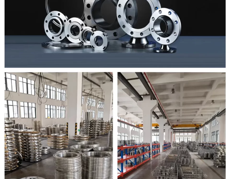
Reliable Slip-On Flange Manufacturing
Available in sizes NPS 1/2″ to 24″ (and larger) across all pressure classes. ISO 9001:2015 Certified Production.
Keywords: Slip-On Flange, SO Flange Dimensions, Class 150 Slip-On Flange, Stainless Steel Slip-On Flange, HG/T20592 SO Flange, ASME B16.5 Dimensions.
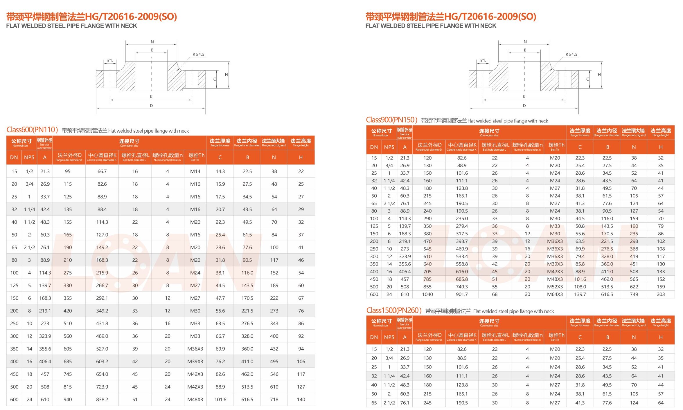
6. High-Pressure Dimensional Matrices (Class 900 – 1500)
Slip-On flanges in higher pressure classes (Class 900 and 1500) are engineered with significantly increased thicknesses and larger bolting patterns to maintain seal integrity under extreme mechanical stress.
Matrix D: ASME Class 900 (PN150) Slip-On Flange
| NPS (Inch) | Pipe OD (A) | Flange OD (D) | PCD (K) | Bolt Holes (n) | Thick (C) | Inner Dia (B) | Hub Dia (N) | Height (H) |
|---|---|---|---|---|---|---|---|---|
| 1/2″ | 21.3 | 120 | 82.6 | 4 | 22.3 | 22.5 | 38 | 32 |
| 1″ | 33.7 | 150 | 101.6 | 4 | 28.6 | 34.5 | 52 | 41 |
| 2″ | 60.3 | 215 | 165.1 | 8 | 38.1 | 61.5 | 105 | 57 |
| 4″ | 114.3 | 290 | 235.0 | 8 | 44.5 | 116.0 | 159 | 70 |
| 8″ | 219.1 | 470 | 393.7 | 12 | 63.5 | 221.5 | 298 | 102 |
| 12″ | 323.9 | 610 | 533.4 | 20 | 79.4 | 328.0 | 419 | 117 |
| 24″ | 610.0 | 1040 | 901.7 | 20 | 139.7 | 616.5 | 749 | 203 |
Matrix E: ASME Class 1500 (PN250) Slip-On Flange
| NPS (Inch) | Pipe OD (A) | Flange OD (D) | PCD (K) | Bolt Holes (n) | Thick (C) | Inner Dia (B) | Hub Dia (N) | Height (H) |
|---|---|---|---|---|---|---|---|---|
| 1/2″ | 21.3 | 120 | 82.6 | 4 | 22.3 | 22.5 | 38 | 32 |
| 3/4″ | 26.9 | 130 | 88.9 | 4 | 25.4 | 27.5 | 44 | 35 |
| 1″ | 33.7 | 150 | 101.6 | 4 | 28.6 | 34.5 | 52 | 41 |
| 1 1/2″ | 48.3 | 180 | 123.8 | 4 | 31.8 | 49.5 | 70 | 44 |
| 2 1/2″ | 76.1 | 245 | 190.5 | 8 | 41.3 | 77.6 | 124 | 64 |
7. Slip-On vs. Weld Neck: Engineering Trade-offs
When selecting between a Slip-On (SO) and a Weld Neck (WN) flange, engineering teams must evaluate the specific fatigue life and installation costs of the project.
| Criteria | Slip-On (SO) | Weld Neck (WN) |
|---|---|---|
| Initial Cost | Lower (approx. 1/3 less material/forging) | Higher (due to hub complexity) |
| Installation | Easier alignment; requires 2 fillet welds | Precise alignment needed; requires 1 butt weld |
| Fatigue Life | Calculated at ~1/3 of a Weld Neck flange | Superior resistance to vibration and stress |
| Flow Pattern | May create turbulence due to the internal step | Smooth transition matched to pipe bore |
8. Quality Control & Metrology Standards
To ensure 100% compliance with ASME/DIN specifications, every Slip-On flange undergoes a multi-phase inspection protocol:
- Dimensional Inspection: Verification of Bore (B), Hub Diameter (N), and Flange Thickness (C) using calibrated digital calipers.
- Surface Finish Metrology: Visual and mechanical verification of the Raised Face (RF) finish, typically targeted between 125–250 micro-inches AARH.
- Chemical PMI: Positive Material Identification via X-ray fluorescence (XRF) to confirm alloy grades like F316L or F51.
- Non-Destructive Testing (NDT): Dye penetrant or ultrasonic testing upon request to identify subsurface inclusions in high-stress hub regions.
Engineering Consultation Available
For specialized requirements including custom bore sizes, non-standard facing, or high-alloy requirements (Inconel, Monel, Hastelloy), our technical department provides full design support.
9. Chemical Composition & Metallurgical Requirements
The reliability of a Slip-On flange in corrosive environments is dictated by its alloying elements. The following data represents the maximum weight percentages for standard stainless and carbon steel grades used in SO flange forging.
Table 3: Chemical Analysis of Common Flange Materials
| Grade (ASTM) | C (Max) | Mn (Max) | Cr | Ni | Mo |
|---|---|---|---|---|---|
| A105 (Carbon) | 0.35 | 1.05 | – | – | – |
| F304 (SS) | 0.08 | 2.00 | 18.0-20.0 | 8.0-10.5 | – |
| F316L (SS) | 0.03 | 2.00 | 16.0-18.0 | 10.0-14.0 | 2.0-3.0 |
| F51 (Duplex) | 0.03 | 2.00 | 21.0-23.0 | 4.5-6.5 | 2.5-3.5 |
10. Mechanical Performance Specifications
Slip-On flanges must exhibit specific tensile and yield strengths to withstand the internal hydrostatic pressures and external bolting loads of a piping network.
Table 4: Mechanical Property Minimums
| Property | ASTM A105 | ASTM A182 F304 | ASTM A182 F316L |
|---|---|---|---|
| Tensile Strength (MPa) | 485 min | 515 min | 485 min |
| Yield Strength (MPa) | 250 min | 205 min | 170 min |
| Elongation (%) | 22 min | 30 min | 30 min |
| Hardness (HBW) | ≤ 187 | ≤ 201 | ≤ 201 |
11. Weight Reference Chart for Logistics
The following weights are theoretical estimates for ASME B16.5 Slip-On Flanges with a Raised Face (RF). These values are essential for calculating freight costs and structural support requirements.
Table 5: Estimated Weights (kg) per Pressure Class
| NPS (Size) | Class 150 | Class 300 | Class 600 | Class 1500 |
|---|---|---|---|---|
| 1/2″ | 0.5 | 0.9 | 1.1 | 3.5 |
| 1″ | 1.1 | 1.6 | 2.6 | 4.5 |
| 2″ | 2.5 | 3.4 | 5.1 | 12.5 |
| 4″ | 6.4 | 10.5 | 19.5 | 35.5 |
| 6″ | 9.5 | 18.0 | 35.0 | 75.0 |
| 12″ | 40.0 | 55.0 | 110.0 | 305.0 |
12. Required Procurement Specifications
To ensure prompt and accurate fulfillment, please include the following parameters in your RFQ:
- Nominal Pipe Size (NPS)
- Pressure Rating (Class)
- Face Type (RF, FF, RTJ)
- Material Specification (ASTM/ASME)
- Bore Schedule (e.g., Sch 40S)
- Quantity & Surface Coating
###CLASS 150###
| Nominal size | Steel Pipe outer diameter | Connection size | flange thickness | flange inner diameter | flange neck big end | flange height | |||||
|---|---|---|---|---|---|---|---|---|---|---|---|
| DN | NPS | A | Flange outer diameter D | Central circle diameter K | Bolt hole diameter L | Number of bolt holes n | Bolt Th | C | B | N | H |
| 15 | 1/2 | 21.3 | 90 | 60.3 | 16 | 4 | M14 | 9.6 | 22.5 | 30 | 14 |
| 20 | 3/4 | 26.9 | 100 | 69.9 | 16 | 4 | M14 | 11.2 | 27.5 | 38 | 14 |
| 25 | 1 | 33.7 | 110 | 79.4 | 16 | 4 | M14 | 12.7 | 34.5 | 49 | 16 |
| 32 | 1 1/4 | 42.4 | 115 | 88.9 | 16 | 4 | M14 | 14.3 | 43.5 | 59 | 19 |
| 40 | 1 1/2 | 48.3 | 125 | 98.4 | 16 | 4 | M14 | 15.9 | 49.5 | 65 | 21 |
| 50 | 2 | 60.3 | 150 | 120.7 | 18 | 4 | M16 | 17.5 | 61.5 | 78 | 24 |
| 65 | 2 1/2 | 76.1 | 180 | 139.7 | 18 | 4 | M16 | 20.7 | 77.6 | 90 | 27 |
| 80 | 3 | 88.9 | 190 | 152.4 | 18 | 4 | M16 | 22.3 | 90.5 | 108 | 29 |
| 100 | 4 | 114.3 | 230 | 190.5 | 18 | 8 | M16 | 22.3 | 116.0 | 135 | 32 |
| 125 | 5 | 139.7 | 255 | 215.9 | 22 | 8 | M20 | 22.3 | 143.5 | 164 | 35 |
| 150 | 6 | 168.3 | 280 | 241.3 | 22 | 8 | M20 | 23.9 | 170.5 | 192 | 38 |
| 200 | 8 | 219.1 | 345 | 298.5 | 22 | 8 | M20 | 27.0 | 221.5 | 246 | 43 |
| 250 | 10 | 273.0 | 405 | 362 | 26 | 12 | M24 | 28.6 | 276.5 | 305 | 48 |
| 300 | 12 | 323.9 | 485 | 431.8 | 26 | 12 | M24 | 30.2 | 328.0 | 365 | 54 |
| 350 | 14 | 355.6 | 535 | 476.3 | 30 | 12 | M27 | 33.4 | 360.0 | 400 | 56 |
| 400 | 16 | 406.4 | 595 | 539.8 | 30 | 16 | M27 | 35.0 | 411.0 | 457 | 62 |
| 450 | 18 | 457 | 635 | 577.9 | 33 | 16 | M30 | 38.1 | 462.0 | 505 | 67 |
| 500 | 20 | 508 | 700 | 635 | 33 | 20 | M30 | 41.3 | 513.5 | 559 | 71 |
| 600 | 24 | 610 | 815 | 749.3 | 36 | 20 | M33 | 46.1 | 616.5 | 663 | 81 |
###CLASS 300###
| Nominal size | Steel Pipe outer diameter | Connection size | flange thickness | flange inner diameter | flange neck big end | flange height | |||||
|---|---|---|---|---|---|---|---|---|---|---|---|
| DN | NPS | A | Flange outer diameter D | Central circle diameter K | Bolt hole diameter L | Number of bolt holes n | Bolt Th | C | B | N | H |
| 15 | 1/2 | 21.3 | 95 | 66.7 | 16 | 4 | M14 | 12.7 | 22.5 | 38 | 21 |
| 20 | 3/4 | 26.9 | 115 | 82.6 | 18 | 4 | M16 | 14.3 | 27.5 | 48 | 24 |
| 25 | 1 | 33.7 | 125 | 88.9 | 18 | 4 | M16 | 15.9 | 34.5 | 54 | 25 |
| 32 | 1 1/4 | 42.4 | 135 | 98.4 | 18 | 4 | M16 | 17.5 | 43.5 | 64 | 25 |
| 40 | 1 1/2 | 48.3 | 155 | 114.3 | 22 | 4 | M20 | 19.1 | 49.5 | 70 | 29 |
| 50 | 2 | 60.3 | 165 | 127 | 18 | 8 | M16 | 20.7 | 61.5 | 84 | 32 |
| 65 | 2 1/2 | 76.1 | 190 | 149.2 | 22 | 8 | M20 | 23.9 | 77.6 | 100 | 37 |
| 80 | 3 | 88.9 | 210 | 168.3 | 22 | 8 | M20 | 27 | 90.5 | 117 | 41 |
| 100 | 4 | 114.3 | 255 | 200 | 22 | 8 | M20 | 30.2 | 116 | 146 | 46 |
| 125 | 5 | 139.7 | 280 | 235 | 22 | 8 | M20 | 33.4 | 143.5 | 178 | 49 |
| 150 | 6 | 168.3 | 320 | 269.9 | 22 | 12 | M20 | 35 | 170.5 | 206 | 51 |
| 200 | 8 | 219.1 | 380 | 330.2 | 26 | 12 | M24 | 39.7 | 221.5 | 260 | 60 |
| 250 | 10 | 273 | 445 | 387.4 | 30 | 16 | M27 | 46.1 | 276.5 | 321 | 65 |
| 300 | 12 | 323.9 | 520 | 450.8 | 33 | 16 | M30 | 49.3 | 328 | 375 | 71 |
| 350 | 14 | 355.6 | 585 | 514.4 | 33 | 20 | M30 | 52.4 | 360 | 425 | 75 |
| 400 | 16 | 406.4 | 650 | 571.5 | 36 | 20 | M33 | 55.6 | 411 | 483 | 81 |
| 450 | 18 | 457 | 710 | 628.6 | 36 | 24 | M33 | 58.8 | 462 | 533 | 87 |
| 500 | 20 | 508 | 775 | 685.8 | 36 | 24 | M33 | 62 | 513.5 | 587 | 94 |
| 600 | 24 | 610 | 915 | 812.8 | 42 | 24 | M39X3 | 68.3 | 616.5 | 702 | 105 |
###CLASS 600###
| Nominal size | Steel Pipe outer diameter | Connection size | flange thickness | flange inner diameter | flange neck big end | flange height | |||||
|---|---|---|---|---|---|---|---|---|---|---|---|
| DN | NPS | A | Flange outer diameter D | Central circle diameter K | Bolt hole diameter L | Number of bolt holes n | Bolt Th | C | B | N | H |
| 15 | 1/2 | 21.3 | 95 | 66.7 | 16 | 4 | M14 | 14.3 | 22.5 | 38 | 22 |
| 20 | 3/4 | 26.9 | 115 | 82.6 | 18 | 4 | M16 | 15.9 | 27.5 | 48 | 25 |
| 25 | 1 | 33.7 | 125 | 88.9 | 18 | 4 | M16 | 17.5 | 34.5 | 54 | 27 |
| 32 | 1 1/4 | 42.4 | 135 | 88.4 | 18 | 4 | M16 | 20.7 | 43.5 | 64 | 29 |
| 40 | 1 1/2 | 48.3 | 155 | 114.3 | 22 | 4 | M20 | 22.3 | 49.5 | 70 | 32 |
| 50 | 2 | 60.3 | 165 | 127 | 18 | 8 | M16 | 25.4 | 61.5 | 84 | 37 |
| 65 | 2 1/2 | 76.1 | 190 | 149.2 | 22 | 8 | M20 | 28.6 | 77.6 | 100 | 41 |
| 80 | 3 | 88.9 | 210 | 168.3 | 22 | 8 | M20 | 31.8 | 90.5 | 117 | 46 |
| 100 | 4 | 114.3 | 275 | 215.9 | 26 | 8 | M24 | 38.1 | 116 | 152 | 54 |
| 125 | 5 | 139.7 | 330 | 266.7 | 30 | 8 | M27 | 44.5 | 143.5 | 189 | 60 |
| 150 | 6 | 168.3 | 355 | 292.1 | 30 | 12 | M27 | 47.7 | 170.5 | 222 | 67 |
| 200 | 8 | 219.1 | 420 | 349.2 | 33 | 12 | M30 | 55.6 | 221.5 | 273 | 76 |
| 250 | 10 | 273 | 510 | 431.8 | 36 | 16 | M33 | 63.5 | 276.5 | 343 | 86 |
| 300 | 12 | 323.9 | 560 | 489 | 36 | 20 | M33 | 66.7 | 328 | 400 | 92 |
| 350 | 14 | 355.6 | 605 | 527 | 39 | 20 | M36X3 | 69.9 | 360 | 432 | 94 |
| 400 | 16 | 406.4 | 685 | 603.2 | 42 | 20 | M39X3 | 76.2 | 411 | 495 | 106 |
| 450 | 18 | 457 | 745 | 654 | 45 | 20 | M42X3 | 82.6 | 462 | 546 | 117 |
| 500 | 20 | 508 | 815 | 723.9 | 45 | 24 | M42X3 | 88.9 | 513.5 | 610 | 127 |
| 600 | 24 | 610 | 940 | 838.2 | 51 | 24 | M48X3 | 101.6 | 616.5 | 718 | 140 |
###CLASS 900###
| Nominal size | Steel Pipe outer diameter | Connection size | flange thickness | flange inner diameter | flange neck big end | flange height | |||||
|---|---|---|---|---|---|---|---|---|---|---|---|
| DN | NPS | A | Flange outer diameter D | Central circle diameter K | Bolt hole diameter L | Number of bolt holes n | Bolt Th | C | B | N | H |
| 15 | 1/2 | 21.3 | 120 | 82.6 | 22 | 4 | M20 | 22.3 | 22.5 | 38 | 32 |
| 20 | 3/4 | 26.9 | 130 | 88.9 | 22 | 4 | M20 | 25.4 | 27.5 | 44 | 35 |
| 25 | 1 | 33.7 | 150 | 101.6 | 26 | 4 | M24 | 28.6 | 34.5 | 52 | 41 |
| 32 | 1 1/4 | 42.4 | 160 | 111.1 | 26 | 4 | M24 | 28.6 | 43.5 | 64 | 41 |
| 40 | 1 1/2 | 48.3 | 180 | 123.8 | 30 | 4 | M27 | 31.8 | 49.5 | 70 | 44 |
| 50 | 2 | 60.3 | 215 | 165.1 | 26 | 8 | M24 | 38.1 | 61.5 | 105 | 57 |
| 65 | 2 1/2 | 76.1 | 245 | 190.5 | 30 | 8 | M27 | 41.3 | 77.6 | 124 | 64 |
| 80 | 3 | 88.9 | 240 | 190.5 | 26 | 8 | M24 | 38.1 | 90.5 | 127 | 54 |
| 100 | 4 | 114.3 | 290 | 235 | 33 | 8 | M30 | 44.5 | 116 | 159 | 70 |
| 125 | 5 | 139.7 | 350 | 279.4 | 36 | 8 | M33 | 50.8 | 143.5 | 190 | 79 |
| 150 | 6 | 168.3 | 380 | 317.5 | 33 | 12 | M30 | 55.6 | 170.5 | 235 | 86 |
| 200 | 8 | 219.1 | 470 | 393.7 | 39 | 12 | M36X3 | 63.5 | 221.5 | 298 | 102 |
| 250 | 10 | 273 | 545 | 469.9 | 39 | 16 | M36X3 | 69.9 | 276.5 | 368 | 108 |
| 300 | 12 | 323.9 | 610 | 533.4 | 39 | 20 | M36X3 | 79.4 | 328 | 419 | 117 |
| 350 | 14 | 355.6 | 640 | 558.8 | 42 | 20 | M39X3 | 85.8 | 360 | 451 | 130 |
| 400 | 16 | 406.4 | 705 | 616 | 45 | 20 | M42X3 | 88.9 | 411 | 508 | 133 |
| 450 | 18 | 457 | 785 | 685.8 | 51 | 20 | M48X3 | 101.6 | 462 | 565 | 152 |
| 500 | 20 | 508 | 855 | 749.3 | 55 | 20 | M52X3 | 108 | 513.5 | 622 | 159 |
| 600 | 24 | 610 | 1040 | 901.7 | 68 | 20 | M64X3 | 139.7 | 616.5 | 749 | 203 |
###CLASS 1500###
| Nominal size | Steel Pipe outer diameter | Connection size | flange thickness | flange inner diameter | flange neck big end | flange height | |||||
|---|---|---|---|---|---|---|---|---|---|---|---|
| DN | NPS | A | Flange outer diameter D | Central circle diameter K | Bolt hole diameter L | Number of bolt holes n | Bolt Th | C | B | N | H |
| 15 | 1/2 | 21.3 | 120 | 82.6 | 22 | 4 | M20 | 22.3 | 22.5 | 38 | 32 |
| 20 | 3/4 | 26.9 | 130 | 88.9 | 22 | 4 | M20 | 25.4 | 27.5 | 44 | 35 |
| 25 | 1 | 33.7 | 150 | 101.6 | 26 | 4 | M24 | 28.6 | 34.5 | 52 | 41 |
| 32 | 1 1/4 | 42.4 | 160 | 111.1 | 26 | 4 | M24 | 28.6 | 43.5 | 64 | 41 |
| 40 | 1 1/2 | 48.3 | 180 | 123.8 | 30 | 4 | M27 | 31.8 | 49.5 | 70 | 44 |
| 50 | 2 | 60.3 | 215 | 165.1 | 26 | 8 | M24 | 38.1 | 61.5 | 105 | 57 |
| 65 | 2 1/2 | 76.1 | 245 | 190.5 | 30 | 8 | M27 | 41.3 | 77.6 | 124 | 64 |
🔧 Slip-On Flanges
Common Issues & Solutions
1. Persistent leak at gasket after bolt tightening — why does it still leak?
high frequency
📌 Root cause: Slip-On flanges require double-sided fillet welds (inner + outer). Weld distortion, excessive weld height causing sealing face warp, or insufficient pipe insertion depth prevents uniform gasket compression. Uneven bolt preload and incorrect gasket selection also contribute.
✅ Professional countermeasures:
- ✔ Ensure pipe insertion depth follows standards (typically ⅔ of flange thickness, not obstructing bolt holes) leaving space for fillet welds without sealing face deformation.
- ✔ Use staggered / back-step welding sequence; control heat input and check flatness after welding (≤0.25mm/m).
- ✔ Choose appropriate gasket (e.g., spiral wound, flexible graphite composite). Follow torque sequence (3~4 steps cross pattern).
- ✔ For minor weeping, perform hot-torquing (if applicable) or recalibrate bolt load; inspect sealing faces for scratches.
2. Cracks appear at flange-to-pipe fillet welds after period of service (vibration/cycling)?
📌 Failure background: Slip-On flanges rely on fillet welds (outer + inner optional) which are weaker than WN flanges. Under high bending moment, vibration or thermal cycling, stress concentration at weld root can cause fatigue cracks. Moreover, inadequate weld leg size or lack of fusion accelerates failure.
✅ Systematic solutions:
- 🔹 Per ASME B31.3, outer fillet weld throat must be at least equal to pipe wall thickness or flange hub thickness. For critical services, apply full penetration weld or inner seal weld.
- 🔹 Add supports/dampers for high-vibration lines (reciprocating compressors, pump discharges) to reduce cyclic stress.
- 🔹 Use matching filler metal; for corrosive media, perform PT/MT on welds and consider corrosion resistant alloy.
- 🔹 If cracks appear, evaluate repair welding or replace with Weld Neck flange for reliability.
📐 Design recommendation: For design pressures beyond Class 300 or severe thermal transients, always prefer Weld Neck flanges. Slip-On flanges are best for ambient / low pressure (≤ PN40 / Class 150~300) non-critical systems.
3. Crevice corrosion / pitting due to stagnant fluid between flange bore and pipe OD?
📌 Mechanism: The small clearance (1~3mm) between Slip-On flange bore and pipe outer diameter can trap moisture or process fluids, creating an aggressive crevice corrosion environment. Stainless steel and carbon steel are vulnerable, especially in chlorides or acidic media. If the inner side is not continuously seal-welded, liquid accumulation accelerates pitting.
✅ Prevention & maintenance practices:
- 🛡️ For critical / corrosive services, apply continuous inner fillet welding or seal weld to eliminate crevice paths.
- 🛡️ Upgrade material (316L, Duplex, or lined flanges). For carbon steel, use high-quality coating or hot-dip galvanizing.
- 🛡️ Prior to service, fill flange clearance with high-temperature flange sealant (e.g., Loctite 567) respecting temperature & process limits.
- 🛡️ Periodic UT thickness monitoring and check chloride/water content in process media.
4. Flange face tilts or opens after bolt tightening, causing misalignment?
📌 Common causes: Slip-On flanges are relatively thin and lack the reinforcing long hub of WN flanges. Excessive bolt preload or gasket crushing results in flange warping (Belleville deformation). Furthermore, if pipe end is not perpendicular to flange face or insertion depth varies, uneven tilting occurs.
✅ Precision alignment methods:
- 🎯 Use torque wrench + hydraulic tensioner with crisscross pattern in steps. Refer to ASME PCC-1 torque values.
- 🎯 Check parallelism of flange faces before assembly; adjust with gasket compensation or rework pipe bevel to ensure perpendicularity.
- 🎯 For large diameter thin flanges, consider tapered washers or load distribution washers, and add backing support to reduce bending moment.
- 🎯 If deformation exceeds limits in design, upgrade pressure class or change to Weld Neck / Lap Joint flanges.
⚠️ Rule of thumb: Bolt torque for Slip-On flanges should not exceed 75% of material yield strength; flexible graphite gaskets help absorb installation tolerances.
5. Misapplied in high-temperature / high-pressure steam lines, leading to rupture risk?
📌 Awareness gap: Many engineers incorrectly assume Slip-On flanges can be used at any condition as long as class rating matches. However, ASME B16.5 states: Slip-On flanges are not recommended for severe cyclic or extreme high-temperature services (carbon steel above 400°C experiences significant strength reduction). Stress concentration at fillet weld root and poor fatigue life cause failure under thermal shocks.
✅ Safe application boundaries & alternatives:
- 🏭 Applicable envelope: -29°C to 200°C (carbon steel), design pressure ≤ 2.0MPa (Class 150) or Class 300 with non-cyclic loading.
- 🏭 For high-pressure steam (≥1.6MPa, temp ≥250°C) or thermal fatigue conditions, use Weld Neck flanges to eliminate abrupt stress transition.
- 🏭 If space constraints force the use of Slip-On flanges, perform FEA for creep-fatigue and increase NDT frequency (weekly PAUT/TOFD).
- 🏭 Strictly adhere to piping class and equipment nameplates; never substitute without engineering approval.
6. Why is insufficient or excessive pipe insertion depth a critical defect?
📌 Severity: Slip-On flange bore is slip-fit. Insufficient insertion prevents proper inner seal welding or reduces fillet weld coverage, weakening the joint. Excessive insertion blocks bolt holes or protrudes onto gasket seating surface, compromising sealing and causing flow turbulence.
✅ Standard work practices:
- 📐 Per ASME B31.1/B31.3, pipe should be inserted to half to two-thirds of flange thickness, leaving 3~5mm from pipe end to sealing face (avoid gasket interference).
- 📐 Mark insertion depth on pipe before assembly and use depth gauge for verification. For DN ≥200, tack-weld and recheck alignment.
- 📐 If inner weld access is blocked, pipe inserted too deep; cut and rework. Never force alignment by over-welding.
- 📐 For corrosive media, flush pipe end with flange inner face plus inner seal weld to eliminate dead zones.
🔔 Proven fact: Proper insertion plus double-sided fillet welding achieves 80~90% of the mechanical strength of a weld neck flange — essential for long service life.
7. Bolts seized, cannot be disassembled during maintenance — forcing destructive cutting?
📌 Frequent in outdoor/humid environments: Corrosion products accumulate in bolt holes and nut clearances. Combined with thin flange geometry, excessive force during disassembly may distort flange. Since the flange is welded to the pipe, rotating the flange to relieve stress is impossible.
✅ Maintenance & prevention strategies:
- 🛢️ Apply high-temperature anti-seize (nickel or copper based) on bolt threads during initial assembly; for stainless bolts use dedicated anti-galling compound.
- 🛢️ Consider increasing flange outer diameter or using heavy hex nuts with extended threads to reduce thread seizure.
- 🛢️ Before disassembly, soak with penetrating lubricant, use impact wrench on low setting; for severe seizure, heat nut to 350°C (carbon steel) and turn out quickly.
- 🛢️ For improved maintainability, use stainless or coated bolts and schedule periodic bolt tension checks.
💡 Tip: If flange is stuck and must be preserved, thread repair inserts can be applied, but it requires specialized tooling. Keep spare lap joint flanges for critical lines.
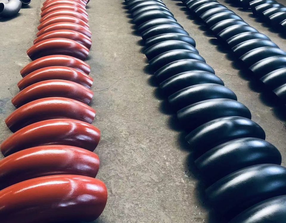
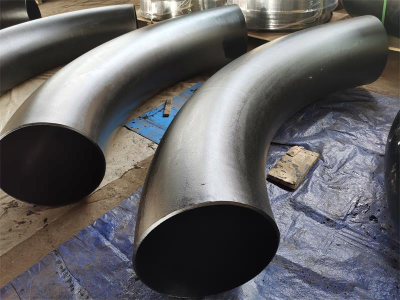
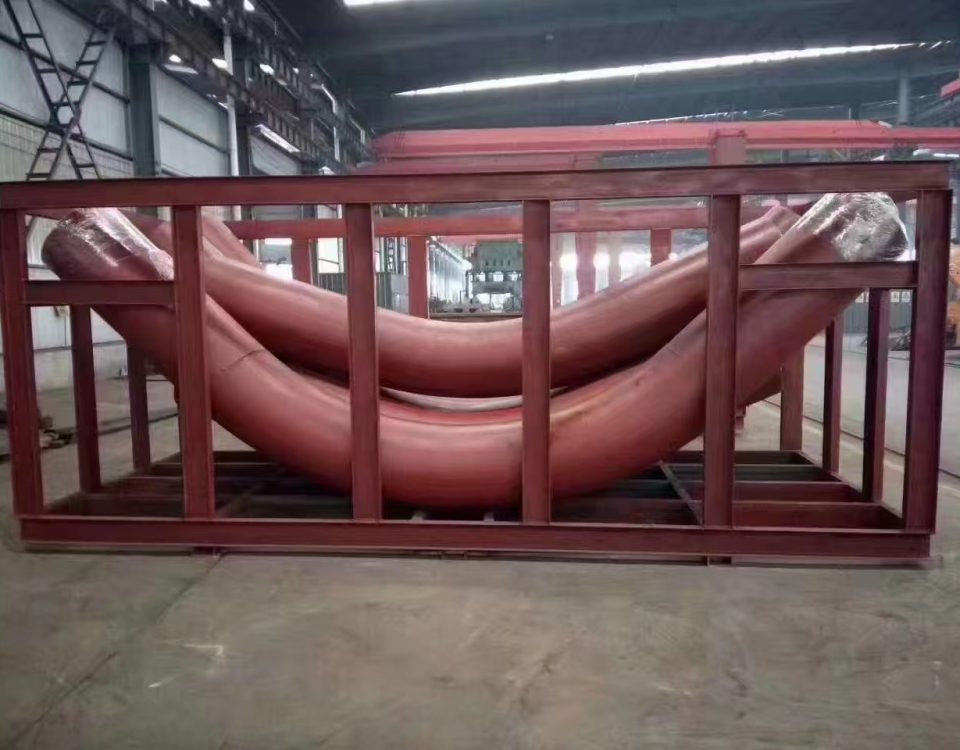
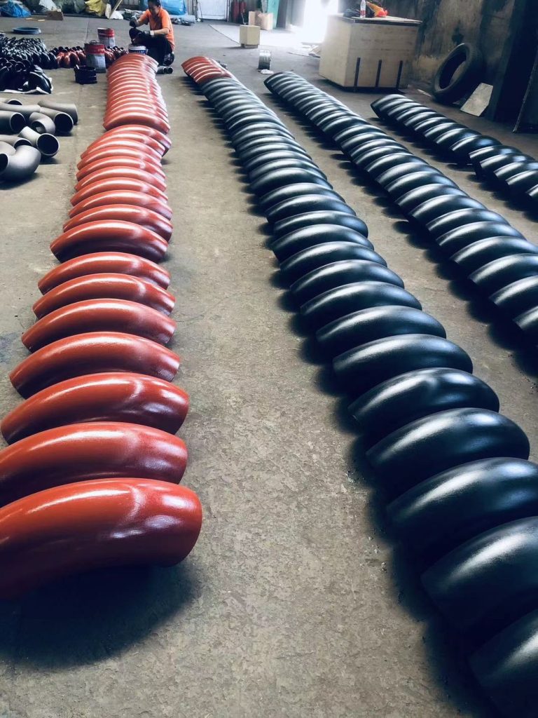
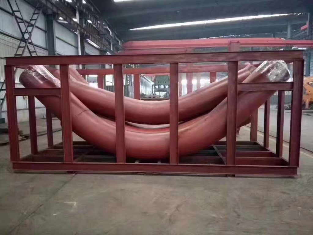
Induction bends come in standard bend angles (e.g. 45°, 90°, etc.) or can be custom made to specific bend angles. Compound bends (out-of-plane) bends in a single joint of pipe can also be produced. The bend radius is specified as a function of the diameter. For example, common bend radii for induction bends are 3D, 5D and 7D, where D is the nominal pipe diameter.
Duplex 2205 and Super Duplex 2507 stainless steel flanges are characterized by their high yield strength, which is twice that of the annealed yield strength of typical austenitic stainless steels, like 304 and 316 stainless steel flanges. Because of this, Duplex 2205 and Super Duplex 2507 steel are some of the most common grades of duplex used for flanges with Super Duplex 2507 flanges being the more corrosion resistant grade of the two.