
Slip-On Flanges (SO)
May 9, 2026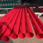
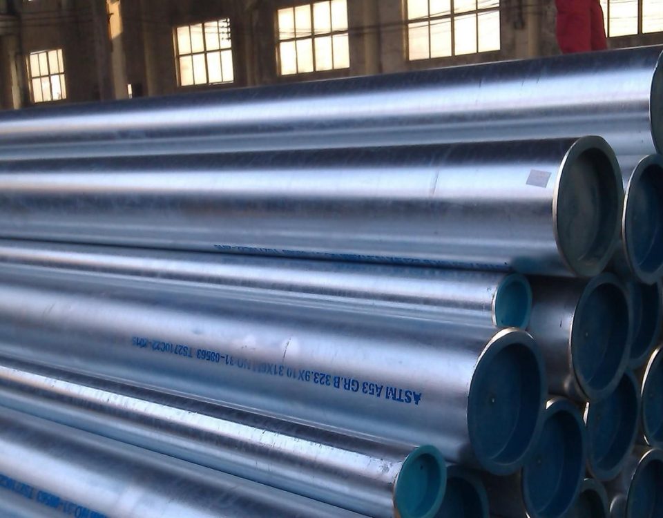
ASTM A135 Fire Sprinkler Pipes
May 23, 2026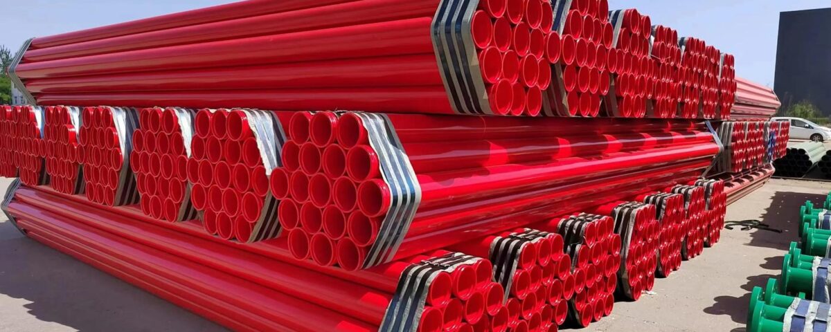
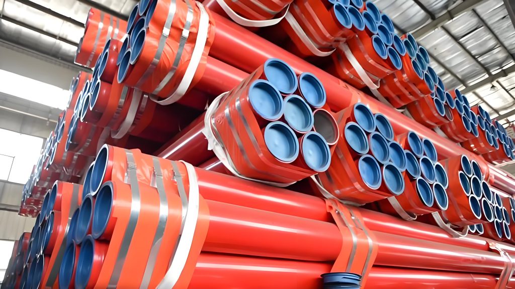
UL 852 Fire Sprinkler Pipes: Comprehensive Engineering & Manufacturing Guide
The Definitive Resource for UL 852 Listed Steel Fire Protection Piping Systems: Mechanical Profiles, Dimensional Criteria, Structural Weight Matrices, and Compliance Standards.
2. Comparative Matrix
3. Technical Specifications
4. Dimensional Tables
5. Metallurgical Analysis
6. Verification Protocols
1. Regulatory Framework: Understanding Underwriters Laboratories Standard 852
In modern structural fire suppression systems, the selection of distribution piping controls system survival limits during thermal load spikes. UL 852 is a globally standardized safety framework established by Underwriters Laboratories (UL) that dictates the manufacturing criteria, mechanical thresholds, testing protocols, and certification boundaries for steel sprinkler pipe configurations deployed within commercial, industrial, and residential fire protection infrastructures.
The designation “852” represents the unique regulatory baseline governing the Standard for Safety of Steel Sprinkler Pipe. This standard establishes severe structural and hydro-mechanical benchmarks, confirming that any pipe displaying the UL Listed stamp can endure high working pressures, resist seismic fatigue, and prevent thermal deformation under extreme heat exposure. By enforcing rigorous chemical composition baselines and structural tolerances, the UL 852 standard mitigates the risk of system failure during high-load deployments.
Key Certification Deliverables Under UL 852:
Pipes certified under the UL 852 regime undergo destructive and non-destructive evaluations including hydrostatic pressure thresholds, extreme bending moments, cyclical vibration endurance, and Corrosion Resistance Ratio (CRR) grading. These steps ensure uninterrupted operation in active fire containment scenarios.
2. Engineering Comparison: Standard Commercial Pipe vs. UL 852 Certified Pipe
Substituting standard structural steel tubes for designated fire-protection piping introduces major failure modes into life-safety systems. The matrix below defines the engineering and regulatory variances between generic commercial piping and authentic UL 852 certified variants.
Table 1: Structural, Safety, and Regulatory Performance Matrix
| Performance Criterion | Generic Commercial Piping | UL 852 Certified Sprinkler Pipe |
|---|---|---|
| Testing Validation | Basic mill hydrostatic verification only; lacks thermal shock assessment. | Exhaustive multi-point qualification (Bending, Vibration, Burst, and NDT). |
| Mechanical Reliability | Unpredicted failure limits under seismic deflection or fluid hammer. | Guaranteed performance at rated working pressures ≥ 175 psi. |
| Corrosion Defense | Variable zinc mass deposition; high propensity for localized pitting. | Verified Corrosion Resistance Ratio (CRR) for long-term interior water stasis. |
| Project Jurisdiction | Frequently rejected by local fire marshals, AXA, and FM Global auditors. | Universal compliance approval across domestic and international civil works. |
| Thermal Yield Point | Rapid structural sagging and elongation under high-temperature exposure. | Retains load-bearing geometry at high temperatures to preserve head alignment. |
3. Technical Parameters & Product Architecture Data Sheet
UL 852 listed piping is produced across clear dimensional schedules and profile types to cover a range of hydraulic configurations. The table below profiles the mechanical limits and processing allowances for authorized manufacturing runs.
Table 2: Comprehensive UL 852 Production Specification Matrix
| Technical Parameter | Standard Compliance & Engineering Boundaries |
|---|---|
| Regulatory Status | Authentic Underwriters Laboratories UL 852 Listed Certification |
| Material Substrates | ASTM A53 Grade A/B, ASTM A795, ASTM A135, or equivalent certified structural carbon steel |
| Dimensional Span | Nominal Pipe Size (NPS) from 1/2-inch to 12-inch inclusive |
| Wall Thickness Tiers | Schedule 5, Schedule 10, Schedule 30, and Schedule 40 engineered profiles |
| Hydrostatic Rating | Maximum Rated Working Pressure: ≥ 175 PSI (1206 KPa) |
| Connection End Machining | Plain End (PE), Roll Grooved (according to standard coupling metrics), or Threaded Ends (ANSI B1.20.1) |
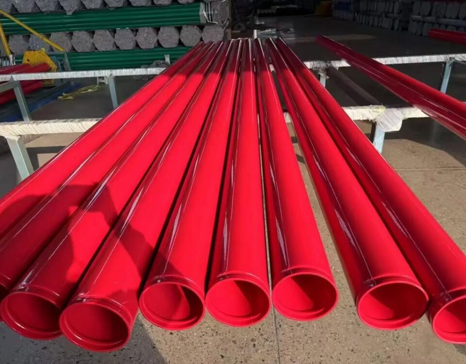
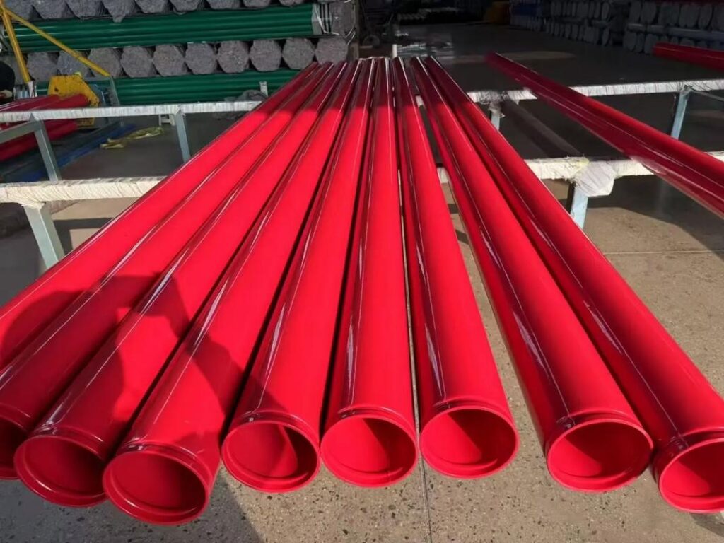
| External Finish Options | Hot-Dip Galvanized (ASTM A153), Fusion Bonded Epoxy (FBE), Red Oxide Primary Primer, or Bare Black Varnish |
| Thermal Operating Envelope | Operational capacity from -30°C (-22°F) up to 80°C (176°F) ambient system temperature |
4. Master Dimensional Reference Matrices
The tables below provide precise engineering tolerances for UL 852 piping across outside diameters, wall thicknesses, and nominal metric translations. These values enable accurate hydraulic friction calculations and mechanical hanger loading designs.
Table 3: Schedule 10 vs. Schedule 40 Wall Thickness & Outer Diameter Configurations
| Nominal Size (NPS) | Nominal Size (DN) | Outside Diameter (mm) | Schedule 10 Profile | Schedule 40 Profile | ||
|---|---|---|---|---|---|---|
| Wall Thickness (mm) | Theoretical Weight (kg/m) | Wall Thickness (mm) | Theoretical Weight (kg/m) | |||
| 1/2″ | 15 | 21.3 | — | — | 2.77 | 1.27 |
| 3/4″ | 20 | 26.7 | — | — | 2.87 | 1.69 |
| 1″ | 25 | 33.4 | 2.77 | 2.09 | 3.38 | 2.50 |
| 1 1/4″ | 32 | 42.2 | 2.77 | 2.69 | 3.56 | 3.39 |
| 1 1/2″ | 40 | 48.3 | 2.77 | 3.11 | 3.68 | 4.05 |
| 2″ | 50 | 60.3 | 2.77 | 3.93 | 3.91 | 5.44 |
| 2 1/2″ | 65 | 73.0 | 3.05 | 5.26 | 5.16 | 8.63 |
| 3″ | 80 | 88.9 | 3.05 | 6.46 | 5.49 | 11.29 |
| 3 1/2″ | 90 | 101.6 | 3.05 | 7.41 | 5.74 | 13.57 |
| 4″ | 100 | 114.3 | 3.05 | 8.37 | 6.02 | 16.07 |
| 5″ | 125 | 141.3 | 3.40 | 11.56 | 6.55 | 21.77 |
| 6″ | 150 | 168.3 | 3.40 | 13.83 | 7.11 | 28.26 |
| 8″ | 200 | 219.1 | 3.76 | 19.96 | 8.18 | 42.55 |
| 10″ | 250 | 273.0 | 4.19 | 27.78 | 9.27 | 60.29 |
5. Metallurgical Profiles & Mechanical Performance Limits
To prevent burst fractures under sudden hydraulic surges, the carbon steel substrates specified by UL 852 must maintain tight metallurgical boundaries. The tables below outline the chemical limit parameters and corresponding structural strength capacities.
Table 4: Chemical Composition Threshold limits (% Weight Maxima)
| Steel Designation | Carbon (C max) | Manganese (Mn max) | Phosphorus (P max) | Sulfur (S max) | Copper (Cu max) |
|---|---|---|---|---|---|
| ASTM A795 Grade A | 0.25% | 0.95% | 0.035% | 0.035% | 0.40% |
| ASTM A795 Grade B | 0.30% | 1.20% | 0.035% | 0.035% | 0.40% |
| ASTM A53 Grade B | 0.30% | 1.20% | 0.050% | 0.045% | 0.40% |
Table 5: Structural Mechanical Property Targets
| Mechanical Property Metric | Grade A Validation Limit | Grade B Validation Limit |
|---|---|---|
| Minimum Tensile Strength | 330 MPa (48,000 psi) | 415 MPa (60,000 psi) |
| Minimum Yield Strength | 205 MPa (30,000 psi) | 240 MPa (35,000 psi) |
| Elongation Core Gauge Limit (2″) | Formulaic Range (Reference Standard) | Formulaic Range (Reference Standard) |
6. Rigorous Quality Control Testing Protocols
Compliance with Underwriters Laboratories status prevents unverified manufacturing tolerances. The QA process requires continuous physical validation across several distinct testing stations:
- Bending Moment Testing: Confirms the pipe can undergo high structural deflections during seismic shifts without structural buckling or weld seam separation.
- Hydrostatic Leakage Verification: 100% of production run units are pressurized to verify absolute pressure containment with no localized structural sweating.
- Cyclical Vibration Assessment: Replicates multi-decade mechanical stress patterns generated by plant machinery or high fluid-velocity flow shifts.
⚠️ CRITICAL MANUFACTURING TRACEABILITY MARKING MANDATE:
Per UL 852 directives, all certified units must display clear stencil stenciling: [Manufacturer Designation] — [UL 852 Listed] — [Schedule / Wall Thickness Profile] — [Nominal Size] — [Rated Fluid Pressure Threshold] — [Corrosion Resistance Ratio / CRR].
7. Structural Deployment Environments
UL 852 listed fire protection conduits are engineered for challenging safety roles across commercial and industrial infrastructure projects:
Commercial Infrastructure
High-rise hospitality centers, institutional medical centers, dense shopping hubs, and corporate office high-rises requiring continuous asset protection loops.
Heavy Manufacturing Zones
Logistics centers, chemical manufacturing spaces, heavy assembly facilities, and automotive manufacturing plants managing high fire-hazard loads.
Global Infrastructure Projects
International transit nodes, public utility complexes, and military installations requiring standardized certifications for safety systems.
Accelerate Project Approval with UL 852 Certified Piping
Ensure project validation, global compliance, and reliable asset safety by integrating certified fire protection components.
Technical Reference: UL 852 Framework | NFPA 13 Compliance | ASTM A795 / A53 Standard Matrix Integration
8. Hydraulic Calculation Balancing & Fluid Friction Loss Variables
When performing automated hydraulic calculations via specialized fire protection software, the internal smoothness of a UL 852 listed pipe directly alters the system’s total friction loss. Engineers utilize the empirical Hazen-Williams equation to determine pressure drop variables across the network footprint.
The value of the Hazen-Williams roughness coefficient ($C$-factor) is determined by the internal surface treatment of the steel tube. Untreated bare black steel profiles introduce greater boundary layer turbulence than precision hot-dip galvanized or internally epoxy-lined alternatives.
Table 6: Hazen-Williams Friction Loss Roughness Coefficients ($C$-Values)
| Internal Piping Material Matrix | NFPA 13 Standard Design $C$-Value | Absolute Hydraulic Roughness ($\epsilon$, mm) |
|---|---|---|
| Unlined Black Steel (Wet Systems) | 120 | 0.045 |
| Hot-Dip Galvanized Steel (Dry / Preaction) | 100 | 0.150 |
| Fusion Bonded Epoxy (FBE) Internal Coating | 140 – 150 | 0.012 |
| Black Carbon Steel (Coroded System Baseline) | 100 | 0.250 |
9. Structural Displacement & Thermal Expansion Limits
Fire safety piping layout blueprints must include calculated allowances for linear expansion and contraction caused by fluctuations in building temperature or high thermal radiation from fire exposure. The mechanical characteristics of carbon steel under thermal duress follow clear geometric linear vectors.
The fundamental mathematical equation utilized by piping engineers to determine overall physical expansion over a distinct longitudinal run length is stated as follows:
Where:
-
$$\Delta L$$Represents the total calculated variation in structural pipe length (mm).
-
$$\alpha$$Represents the primary linear thermal expansion coefficient for structural carbon steel ($11.7 \times 10^{-6} \text{ mm/mm/°C}$ or $6.5 \times 10^{-6} \text{ in/in/°F}$).
-
$$L_0$$Represents the initial unheated length of the pipe run section (mm).
-
$$\Delta T$$Represents the total core temperature delta fluctuation (°C or °F).
Table 7: Linear Thermal Expansion Metrics per 100 Meters of Piping Run
| Temperature Differential ($\Delta T$) | Expansion per 100m – Steel (mm) | Required Structural Hanger Clearance (mm) |
|---|---|---|
| 20°C (68°F) Delta | 23.4 | ≥ 30 |
| 40°C (104°F) Delta | 46.8 | ≥ 60 |
| 60°C (140°F) Delta | 70.2 | ≥ 90 |
| 100°C (212°F) Delta | 117.0 | ≥ 150 |
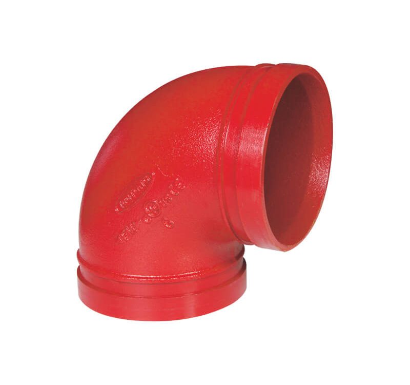
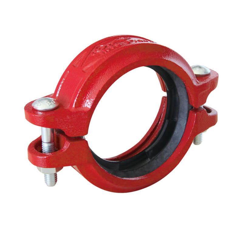
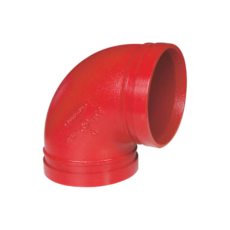
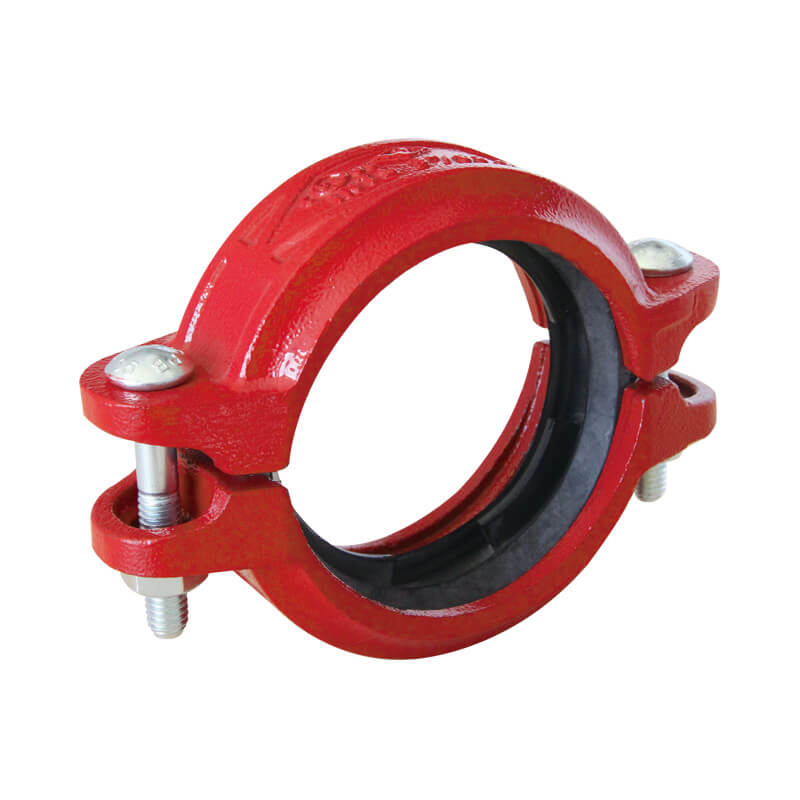
10. Joint Geometry: Roll Groove and Thread Profiling Dimensions
To establish an airtight, pressure-balanced connection point using standardized victaulic couplings or threaded fittings, the pipe ends must be machined to precise geometric specifications. Diverging from these target boundaries can cause gasket pinch or joint separation under high hydraulic loads.
Table 8: Standard Roll Groove Geometry Specifications (ASME / AWWA Reference)
| Nominal Pipe Size (NPS) | Gasket Seat Width “A” (mm) | Groove Width “B” (mm) | Groove Diameter “C” (mm) | Target Groove Depth “D” (mm) |
|---|---|---|---|---|
| 2″ (DN50) | 15.88 | 8.74 | 57.15 | 1.60 |
| 3″ (DN80) | 15.88 | 8.74 | 84.94 | 1.98 |
| 4″ (DN100) | 15.88 | 8.74 | 110.08 | 2.11 |
| 6″ (DN150) | 15.88 | 8.74 | 163.96 | 2.16 |
| 8″ (DN200) | 19.05 | 11.91 | 214.40 | 2.34 |
| 12″ (DN300) | 19.05 | 11.91 | 268.28 | 2.36 |
11. Corrosion Resistance Ratio (CRR) Value Realization
The Corrosion Resistance Ratio (CRR) is a critical engineering factor used to evaluate the long-term structural viability of fire protection pipes relative to a standard Schedule 40 reference tube. A CRR value equal to or greater than 1.0 indicates that the piping wall configuration matches or exceeds the corrosion durability of standard-wall steel.
Lightweight pipelines (such as Schedule 5 or Schedule 10 configurations) frequently deploy premium alloy additions or high-thickness zinc coatings to achieve favorable CRR ratings despite their thinner cross-sections.
Table 9: Definitive Pipeline Corrosion Resistance Ratio Matrix
| Pipe Specification Classification | Wall Profile Thickness Class | Typical Connection Method | Calculated CRR Value Baseline |
|---|---|---|---|
| Standard ASTM A53 Pipe | Schedule 40 | Threaded / Grooved | 1.00 |
| Lightwall Fire Pipe Run | Schedule 10 | Roll Grooved Only | 1.00 – 1.25 (Galv) |
| Ultra Light Fire Pipe Run | Schedule 5 | Specialty Swage / Lock | 0.50 – 0.75 (Bare) |
| Engineered High-Alloy Sprinkler Pipe | Schedule 10 | Roll Grooved / Welded | > 2.00 |
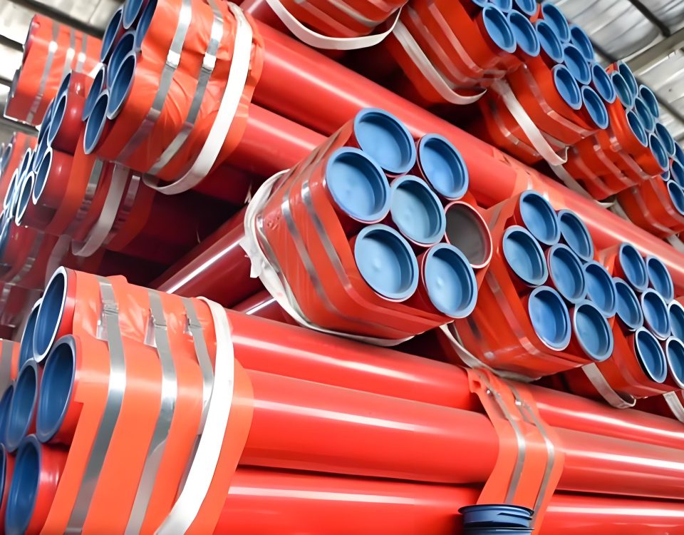
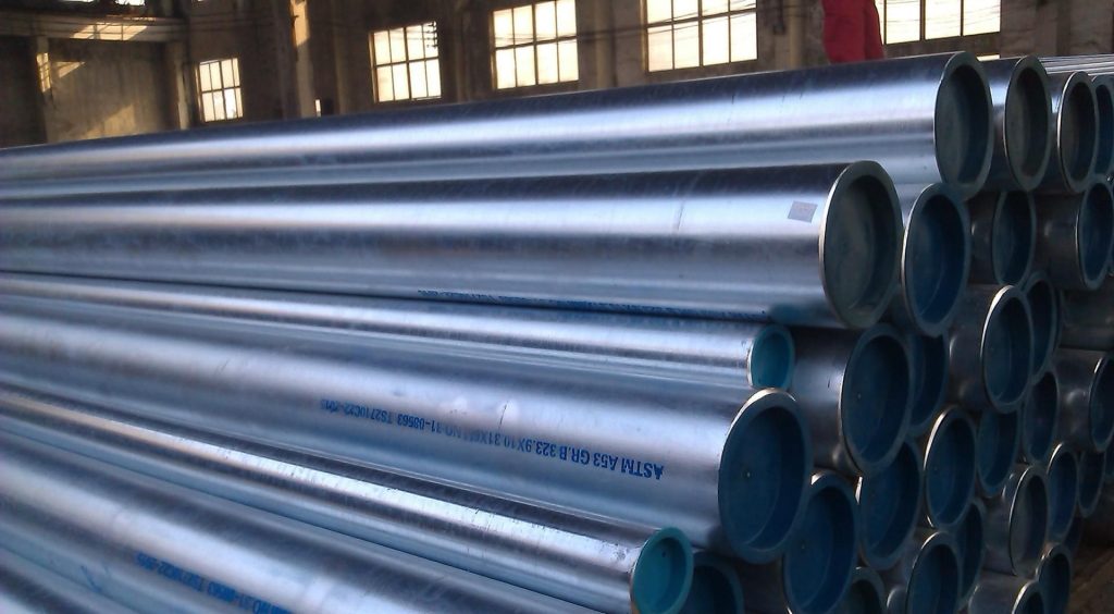
12. Logistics Management: Standard Packaging & Bundle Mass Indices
To optimize shipping container configurations and safely manage job site cranes during material staging, procurement managers rely on standardized bundle counts. The table below details the shipping packing specifications for 6-meter (approx. 20-foot) pipe section runs.
Table 10: Standard Export Freight Bundle Densities (6-Meter Section Standard)
| Nominal Size (NPS) | Pipes per Bundle (Hex Packing) | Est. Schedule 10 Bundle Weight (kg) | Est. Schedule 40 Bundle Weight (kg) |
|---|---|---|---|
| 1″ | 169 | 2,120 | 2,535 |
| 1 1/2″ | 91 | 1,698 | 2,211 |
| 2″ | 61 | 1,438 | 1,991 |
| 3″ | 37 | 1,434 | 2,506 |
| 4″ | 19 | 954 | 1,832 |
| 6″ | 10 | 830 | 1,696 |
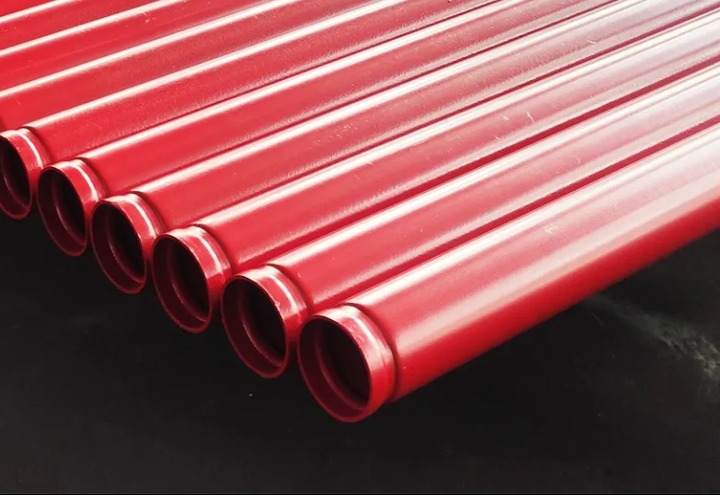
MORE Specification:
O.D.: Φ33.7-Φ219.1 (mm)
Wall thickness: 2.75-5.0 (mm)
Anticorrosive: 1. hot galvanized; 2. powder coating; 3.painting
End state: 1.Grooved; 2. Plain end; 3.screwed & socketed
Function: Fire and water supply system in the building
ASTM A135 (BLACK & GALVANISED) SCH10
| N.D. | O.D. | WALL THICKNESS | NOMINAL WEIGHT | TEST PRESSURE |
| inch | mm | mm | kg/m | Mpa |
| 4/3 | 26.8 | 2.11 | 1.28 | 17.24 |
| 1 | 33.5 | 2.77 | 2.09 | 17.24 |
| 1-1/4 | 42.2 | 2.77 | 2.7 | 16.55 |
| 1-1/2 | 48.3 | 2.77 | 3.1 | 14.48 |
| 2 | 60.3 | 2.77 | 3.93 | 11.72 |
| 2-1/2 | 73 | 3.05 | 5.26 | 10.34 |
| 3 | 88.9 | 3.05 | 6.45 | 8.27 |
| 3-1/2 | 101.6 | 3.05 | 7.41 | 6.89 |
| 4 | 114.3 | 3.05 | 8.36 | 6.21 |
| 5 | 141.3 | 3.40 | 11.58 | 5.86 |
| 6 | 168.3 | 3.40 | 13.84 | 5.02 |
| 8 | 219 | 4.80 | 15.41 | 4.26 |
ASTM A135 (BLACK & GALVANISED) SCH40
| N.D. | O.D. | WALL THICKNESS | NOMINAL WEIGHT | TEST PRESSURE |
| inch | mm | mm | kg/m | Mpa |
| 1/2 | 21.3 | 2.77 | 1.27 | 17.20 |
| 3/4 | 26.8 | 2.87 | 1.68 | 17.20 |
| 1 | 33.5 | 3.38 | 2.50 | 17.20 |
| 1-1/4 | 42.2 | 3.56 | 3.38 | 17.20 |
| 1-1/2 | 48.3 | 3.68 | 4.05 | 17.20 |
| 2 | 60.3 | 3.91 | 5.43 | 16.08 |
| 1-1/2 | 73 | 5.16 | 8.62 | 17.20 |
| 3 | 88.9 | 5.49 | 11.28 | 15.30 |
| 3-1/2 | 101.6 | 5.74 | 13.56 | 14.00 |
| 4 | 114.3 | 6.02 | 16.06 | 13.06 |
| 5 | 141.3 | 6.55 | 21.76 | 11.50 |
| 6 | 168.3 | 7.11 | 28.34 | 10.48 |
| 8 | 219.1 | 8.18 | 36.90 | 7.96 |
ASTM A795 (BLACK & GALVANISED)
| N.D. | O.D. | SCH 10 | SCH 30/40 | ||||||||
| WALL THICKNESS | NOMINAL WEIGHT | WALL THICKNESS | NOMINAL WEIGHT | ||||||||
| (mm) | (inch) | (mm) | (inch) | (mm) | (inch) | (kg/mtrs) | (lbs/ft) | (mm) | (inch) | (kg/mtrs) | (lbs/ft) |
| 15 | 1/2 | 21.30 | 0.84 | —- | —- | —- | —- | 2.77 | 0.109 | 1.27 | 0.85 |
| 20 | 3/4 | 26.70 | 1.05 | 2.11 | 0.083 | 1.28 | 0.96 | 2.87 | 0.113 | 1.69 | 1.13 |
| 25 | 1 | 33.40 | 1.32 | 2.77 | 0.109 | 2.09 | 1.41 | 3.38 | 0.133 | 2.50 | 1.68 |
| 32 | 1-1/4 | 42.20 | 1.66 | 2.77 | 0.109 | 2.69 | 1.81 | 3.56 | 0.14 | 3.39 | 2.27 |
| 40 | 1-1/2 | 48.30 | 1.90 | 2.77 | 0.109 | 3.11 | 2.09 | 3.68 | 0.145 | 4.05 | 2.72 |
| 50 | 2 | 60.30 | 2.38 | 2.77 | 0.109 | 3.93 | 2.64 | 3.91 | 0.154 | 5.45 | 3.66 |
| 65 | 2-1/2 | 73.00 | 2.88 | 3.05 | 0.12 | 5.26 | 3.53 | 5.16 | 0.203 | 8.64 | 5.80 |
| 80 | 3 | 88.90 | 3.50 | 3.05 | 0.12 | 6.46 | 4.34 | 5.49 | 0.216 | 11.29 | 7.58 |
| 90 | 3-1/2 | 101.60 | 4.00 | 3.05 | 0.12 | 7.41 | 4.98 | 5.74 | 0.226 | 13.58 | 9.12 |
| 100 | 4 | 114.30 | 4.50 | 3.05 | 0.12 | 8.37 | 5.62 | 6.02 | 0.237 | 16.09 | 10.80 |
| 125 | 5 | 141.30 | 5.56 | 3.4 | 0.134 | 11.58 | 7.78 | 6.55 | 0.258 | 21.79 | 14.63 |
| 150 | 6 | 168.30 | 6.63 | 3.4 | 0.134 | 13.85 | 9.30 | 7.11 | 0.28 | 28.29 | 18.99 |
| 200 | 8 | 219.10 | 8.63 | 4.78 | 0.188 | 25.26 | 16.96 | 7.04 | 0.277 | 36.82 | 24.72 |
| 250 | 10 | 273.10 | 10.75 | 4.78 | 0.188 | 31.62 | 21.23 | 7.08 | 0.307 | 51.05 | 34.27 |
All system designs should cross-verify specific piping choices against local jurisdictional codes, NFPA guidelines, and the active Underwriters Laboratories certification database.
